LEGO® MINDSTORMS® EV3 Official Software (EV3-G)
 +
Warning
Please Note: You are currently viewing the tutorial for the 【EV3-G Official Software】 environment. If you are using SPIKE or other EV3 software, please click the button above to return to the hub menu and reselect.
Applicable to the LEGO® MINDSTORMS® EV3 Official Software (LabVIEW style interface, often referred to as EV3-G). In this environment, the Pathfinder 8-Way Sensor will be perfectly identified by the LEGO system as an official Infrared Sensor.
Important
Crucial Hardware Communication Delay Warning for EV3 Due to the hardware communication mechanism limitations of the official LEGO EV3 hub, when a program switches between different block modes (e.g., from Proximity to Remote) for reading, the hub will generate a physical communication waiting delay of approximately 0.5 seconds, which can cause the robot to lose control in high-speed competitions. Strong Recommendation: Depending on your task requirements (e.g., only using Remote for PID line following), select ONE block mode at the very beginning of the program and DO NOT switch reading modes midway through the task!
Simulation Description In the official EV3 software, the sensor will be recognized as an Infrared Sensor. Please follow the instructions below to select Proximity / Beacon / Remote modes to read different data.
Read Line Position — Proximity Mode
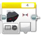
Use the sensor block, select Proximity mode, and read the value to get the line position.
| Returned Value | Range | Description |
|---|---|---|
| Line Position | -8 ~ +8 |
👉 0 = black line is dead center, negative is left, positive is right; ±8 means the line is at the very edge of the sensor.
|
Read 8-Channel Photoelectric Reflection Values — Beacon Mode
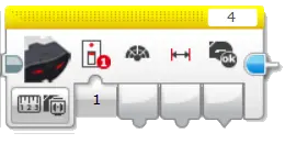
Use the sensor block, select Beacon mode, and read the value list (8 bytes).
| Byte | Content | Range | How to read |
|---|---|---|---|
| 0 | Channel 1 reflectance | 0 ~ 100 | Beacon channel 1 — Heading |
| 1 | Channel 2 reflectance | 0 ~ 100 | Beacon channel 1 — Proximity |
| 2 | Channel 3 reflectance | 0 ~ 100 | Beacon channel 2 — Heading |
| 3 | Channel 4 reflectance | 0 ~ 100 | Beacon channel 2 — Proximity |
| 4 | Channel 5 reflectance | 0 ~ 100 | Beacon channel 3 — Heading |
| 5 | Channel 6 reflectance | 0 ~ 100 | Beacon channel 3 — Proximity |
| 6 | Channel 7 reflectance | 0 ~ 100 | Beacon channel 4 — Heading |
| 7 | Channel 8 reflectance | 0 ~ 100 | Beacon channel 4 — Proximity |
Each value is a calibrated reflectance:
0= darkest (black line),100= brightest (white). Channel 1 is the leftmost sensor (viewed from behind the robot).
Read Position + Width + Boundary Defense — Remote Mode (Recommended for Tactical Competition!)
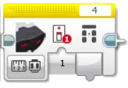
Use the sensor block, select Remote mode, and read the value list (4 bytes).
| Byte | Content Data | Value Range | Tactical Interpretation |
|---|---|---|---|
| Byte 0 | High-Res Position Shift | -100 ~ +100 |
👉 0 represents dead center, negative is left, positive is right. The top choice for ultra-smooth PID error input!
|
| Byte 1 | Feature Line Width | 0 ~ 8 | 👉 Number of triggered sensors. Can be used to detect intersections or T-junctions. |
| Byte 2 | Left Boundary Physical Light Value | 0 ~ 100 |
👉 dataIrCalib[0] (channel 1) The reflected light of the leftmost sensor. 0=pure black, 100=pure white. Can be used to detect track boundaries or forks.
|
| Byte 3 | Right Boundary Physical Light Value | 0 ~ 100 |
👉 dataIrCalib[7] (channel 8) The reflected light of the rightmost sensor. 0=pure black, 100=pure white. Can be used to detect track boundaries or forks.
|
Tactical Fool-Proofing Tip: Byte 2 and Byte 3 in Remote mode allow you to directly obtain the extreme edge light values on both sides of the sensor within EV3-G blocks. If both values are simultaneously less than 20, it means the front of the car has completely entered the horizontal line of an intersection; if one side's value suddenly changes, it means a fork is approaching. This is the ultimate weapon to prevent losing the line!
Download Example Programs
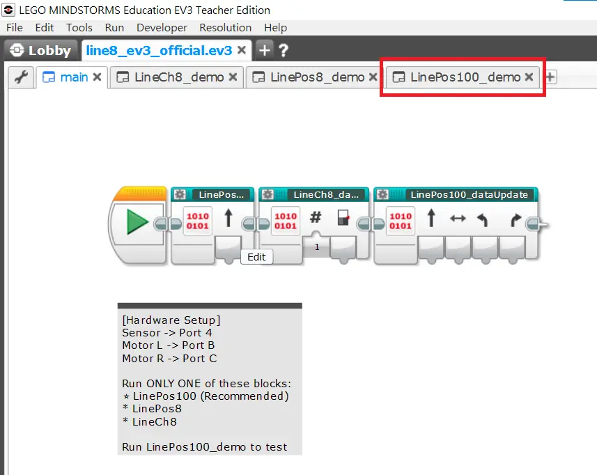
The image above demonstrates the classic PID line-following program structure in EV3-G for the 8-Way Line Follower.
EV3 Exclusive My Blocks Explanation
To make programming in EV3-G more concise and intuitive, the MBC 8-Way Line Follower provides three powerful "My Blocks". During development, you don't need to install cumbersome extension packs; just import the My Blocks, and the system will automatically parse the hardware packets in the background and output the latest sensor data for the motor control logic to use directly.
Here is an introduction to the functions and usage timings of the three core My Blocks:
1. Basic Line Following Block: LinePos8
- Purpose: Quickly read the most basic 8-segment line position, suitable for beginner tutorials and basic left/right steering judgments.
- Output Node:
0_LinePos8. - Value Parsing: The range is between
-8and+8. - Physical Intuition: Negative value when the black line is on the left, 0 when it is dead center, positive value when it is on the right.
2. Competitive High-Precision Block: LinePos100
- Purpose: Obtain high-resolution sub-pixel interpolated positions, the best choice for PID line following. Designed specifically for high-end PID/PD line-following control algorithms (applicable to various racing events), providing extremely smooth correction power. The prerequisite is that the sensor calibration must be fully completed; the more accurate the calibration, the more precise the values.
- Output Nodes:
0_LinePos100: High-precision position, range-100to+100(also maintains the standard of left negative, right positive).0_LineWidth8: Real-time line width detection, the value represents the number of currently triggered sensors (range0to8). Can be used to accurately judge intersections, T-junctions, or the finish stop line.- Left/Right Boundaries: Synchronously read the physical light values of the leftmost and rightmost sensors.
3. Full Array Expansion Block: LineCh8
- Purpose: Thoroughly decode the 8 sensors into independent states. Applicable for writing custom special intersection judgment algorithms, or drawing the status of the 8 sensors directly on the screen of the EV3 hub.
- Output Nodes: Outputs 8 independent values from
s1tos8in one go, perfectly corresponding to the real-time readings of each sensor from left to right.
Tip
Want to learn more advanced line-following control methods? You can take classes from these awesome coaches! They have rich experience in competitions and teaching, guaranteeing you'll learn a lot! 💯