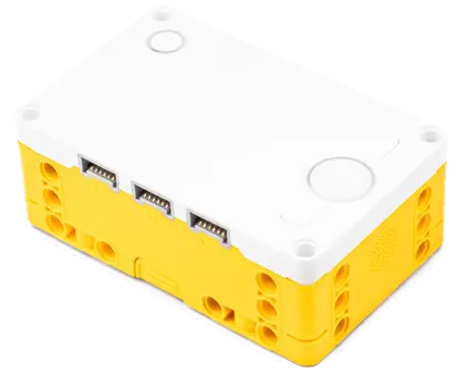
LEGO® Education SPIKE™ Prime Set
 +
Warning
Please Note: You are currently viewing the tutorial for the 【LEGO® Education SPIKE™ Prime Set】 environment. If you are using EV3 or other system software, please click the button above to return to the hub menu and reselect.
This page applies to the LEGO® Education SPIKE™ Prime Set, utilizing the LEGO Education SPIKE 3 App block programming mode.
In this environment, the Pathfinder 8-Way Sensor will be perfectly identified by the LEGO system as an official "SPIKE Color Sensor". To break through the limitations of the official hardware sockets, we utilize special encoding technology to map and package the 8-channel data into the various data channels of the official color sensor, allowing you to read it using the simplest official programming blocks!
Block Command Data Channel Mapping Table
You can directly pull the official block commands of the color sensor in your program to obtain the following mapped data:
| Official Block Command | Mapped Physical Data | Value Range & Decoding Guide |
|---|---|---|
| 🎨 Color | Feature Line Width |
0 ~ 8 👉 Represents the number of sensors stepping on the line. A normal black line is generally 2 ~ 3. If it is an intersection or a large color block, the value will increase significantly, which can be used for intersection protection.
|
| 💡 Reflected Light | Standard Position Shift Value |
0 ~ 16 👉 8 represents dead center, 0 represents far left, 16 represents far right. Reading the value and subtracting 8 gives the line-following position (negative value means black line is on the left, positive means black line is on the right). This value is clear and suitable for PID line following.
|
| 🔴 Red | High-Resolution Smooth Position |
0 ~ 200 👉 100 represents dead center, 0 represents extreme left, 200 represents extreme right. Reading the value and subtracting 100 gives the high-precision line-following position (negative value means black line is on the left, positive means black line is on the right). It uses smart algorithms to provide a higher-precision error margin. Using this mode requires ensuring the sensor is properly calibrated.
|
| 🟢 Green | First 4 Photoelectric Values |
0 ~ 65535 👉 First four photoelectric values: Every 4-bits represent a photoelectric value, with a precision of up to 15 levels (value range 0 ~ 15).
|
| 🔵 Blue | Last 4 Photoelectric Values |
0 ~ 65535 👉 Last four photoelectric values: Every 4-bits represent a photoelectric value, with a precision of up to 15 levels (value range 0 ~ 15).
|
Download Example Programs
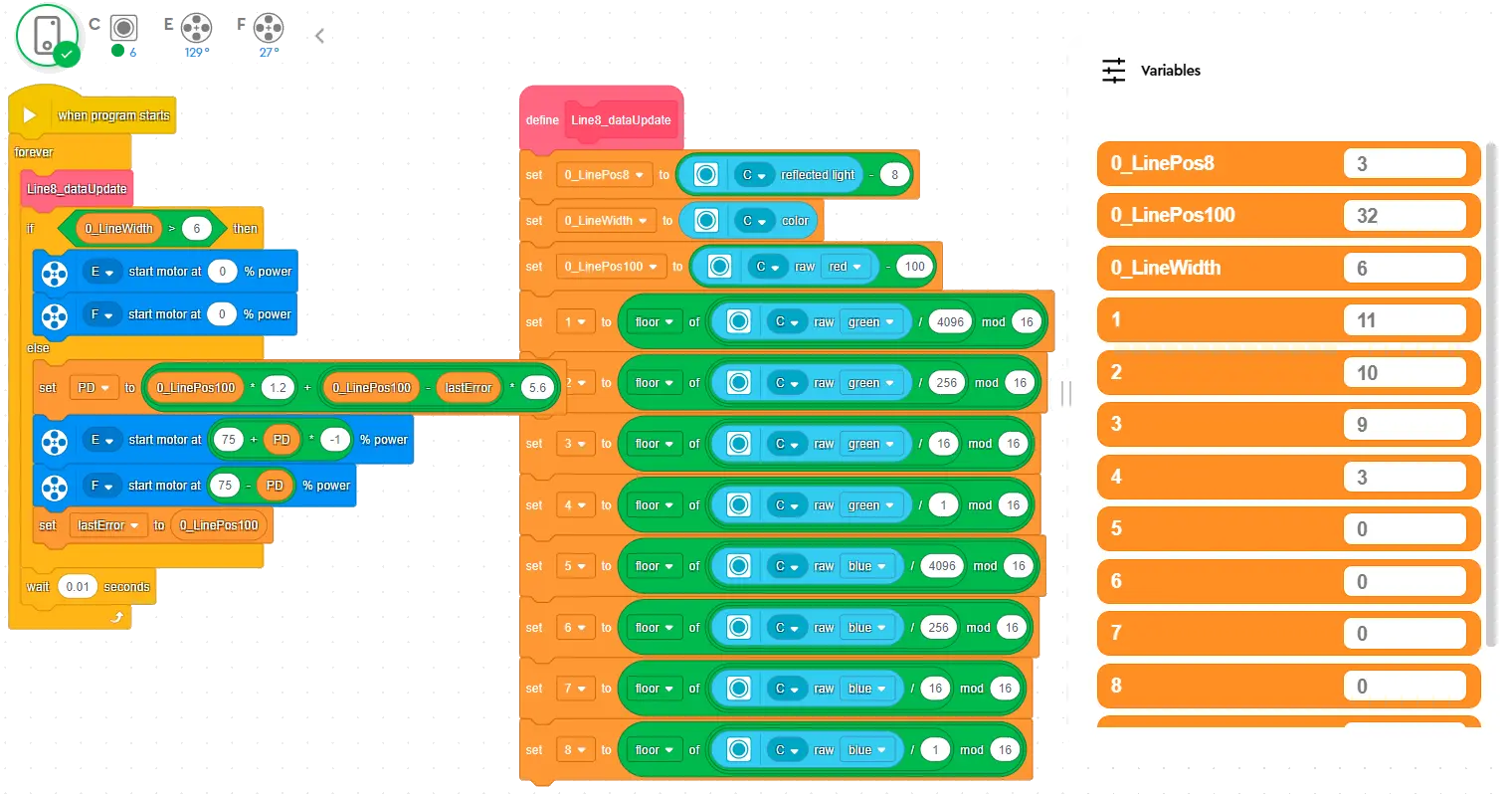
The image above demonstrates the classic PID line-following program structure in the LEGO® Education SPIKE™ App for the 8-Way Line Follower.
After downloading, open it directly using the official LEGO® Education SPIKE™ App.
Tip
Want to learn more advanced line-following control methods? You can take classes from these awesome coaches! They have rich experience in competitions and teaching, guaranteeing you'll learn a lot! 💯