
SharpShot ESP32CAM × Arduino Examples
Back to SharpShot Home | MBC Universal I2C Protocol v2 (advanced)
Warning
Hardware confirmed to work with Arduino; the I2C firmware bench test is still pending. The wiring and examples on this page follow the final MBC I2C Protocol v2 and compile on all three boards. We will remove this notice after the bench test. If you want to use the SharpShot right now, use the SPIKE or EV3 edition first.
This page has 6 examples: 5 for the School edition (color pick, blob tracking) and 1 for the WRO edition (12 color spots). You can copy and upload each example as it is, and every line of the code has an English comment. Never written code before? No problem. Just do them one by one, in order.
Tip
First time using Arduino? Read 🔰 First Time with Arduino: Start from Zero first. In 15 minutes you learn how to install the software, upload a program and see the result.
Wiring (the same for every example)
| SharpShot (product side) | Arduino UNO / Nano | Arduino UNO R4 | ESP32 |
|---|---|---|---|
| 5V | 5V | 5V | 5V (VIN) |
| GND | GND | GND | GND |
| IO3 (= SDA) | A4 | SDA | GPIO 21 |
| IO1 (= SCL) | A5 | SCL | GPIO 22 |
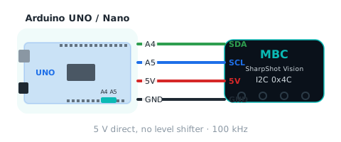
What are IO3 / IO1 on the product side? The SharpShot's hub connector uses the ESP32 pins IO3 and IO1 (the same wires as the EV3 / SPIKE serial editions). With the I2C firmware, IO3 is SDA and IO1 is SCL, and the I2C address is 0x4C. So:
Important
- The SharpShot must be flashed with the I2C firmware. The EV3 and SPIKE editions use the same pins for serial, so only one at a time; they cannot be supported together.
- The hardware wiring is confirmed; the I2C firmware bench test is pending (see the notice at the top).
- First set up sample point S1 and the color to track on the screen on the back of the SharpShot (the settings are stored on the device). The Arduino only reads the results.
- The SharpShot is an ESP32-based slave, so the
delay(2)in the helpers must not be removed.- It needs a few seconds to boot (camera init + screen); the examples wait up to 8 s. Unplug the USB cable before you connect the wires.
Command overview (what this SharpShot can give you)
Think of the SharpShot as a row of numbered "boxes". Each box holds one number (int16). Write [number], then read 2 bytes, and you get one value. Boxes next to each other can be read in one row (up to 16). In the examples, mbcRead(ADDR, number) and mbcReadMany(ADDR, first number, how many, array) do exactly this. The School edition uses 010A, the WRO edition (HUE12) uses 101B and 20~`2B; the high byte of F0` tells you which edition you have.
| Number | Name | Range / unit | Meaning | Used in |
|---|---|---|---|---|
01 |
Hue (School edition) | −1~100 | Hue at sample point S1: red 0/100, yellow about 17, green about 33, cyan about 50, blue about 67, purple about 83; −1 = black/white/gray (saturation < 10); S1 not set = 0 | Examples 2, 3 |
02 |
Saturation | 0~100 | Saturation at S1, higher = more vivid | Examples 2, 3 |
03 |
Brightness | 0~100 | Brightness at S1, higher = brighter | Examples 2, 3 |
04 |
Motion | 0~100 | Whole-image motion, bigger when more of the image changes | Example 2 |
05 |
Blob X | 0~100 | Blob center X, left = 0; not found = 0 | Examples 2, 4, 5 |
06 |
Blob Y | 0~75 | Blob center Y, bottom = 0, top = 75; not found = 0 | Examples 2, 4 |
07 |
Blob width | 0~100 | 0 = not found | Examples 2, 4 |
08 |
Blob height | 0~75 | not found = 0 | Examples 2, 4 |
09 |
Blob area | 0~7500 | width × height | Examples 2, 4 |
0A |
Blob found | 0~1 | 1 = a blob of the target color is in the image (width > 0) | Examples 2, 4, 5 |
10~`1B` |
Spots S1~S12 color code (WRO edition) | 0~255 | 0 |
Example 6 |
20~`2B` |
Spots S1~S12 vividness (WRO edition) | 0~255 | black = 1, white / color = actual saturation; spot off = 0 | Example 6 |
F0 |
Device ID | — | low byte = factory address 0x4C, high byte = 1 School / 2 WRO | Examples 1, 6 |
F1 |
Protocol version | 2 | These examples are written for version 2 | Example 1 |
F2 |
Firmware version | major x 100 + minor | for example 102 = 1.2 | Example 1 |
F3 |
Status flags | bits | b0 ready, b1 blob found (School edition; WRO edition always 0) | Example 1, mbcWaitReady in every example |
F5 |
Seconds since power-on | 0~32767 | If the number gets smaller, the sensor has restarted | Example 1 |
Note
The SharpShot has no write commands (the target color and the flash light are set on the device's screen). A box that does not exist (School edition reading
102B, WRO edition reading010A) reads as-32768(calledMBC_NONEin the examples). You also get-32768when the SharpShot cannot be read. Full specification: MBC Universal I2C Protocol v2.
All Examples
| # | Example | Edition | What you learn | You also need |
|---|---|---|---|---|
| 1 | Say hello to the SharpShot | Both | Check the wiring, read the ID card, tell School / WRO edition apart | Nothing |
| 2 | Print all the values at once | School | See what every box 01~0A holds | A few sheets of colored paper |
| 3 | What color is this? | School | Hue / saturation / brightness → color name | A few sheets of colored paper |
| 4 | Where is the color blob? | School | X / Y / width / height / area / found | An object of the target color |
| 5 | Servo follows the color blob (advanced) | School | Use X to control an angle; servo code for both UNO and ESP32 | SG90 servo |
| 6 | WRO edition: all 12 color spots at once | WRO | Read 12 color codes + 12 vividness values in one go | WRO field |
Tip
Suggested order: 1 → 2 → 3 → 4 → 5. A SharpShot with WRO edition firmware runs 1 → 6.
1️⃣ Say hello to the SharpShot
What it does: Checks that the SharpShot is connected and prints its "ID card" (factory address, School or WRO edition, protocol version, firmware version) and the status flags. Run this one first every time you connect a new SharpShot.
Steps:
- Connect the 4 wires as in the table above, then plug the USB cable into the computer (the SharpShot's screen turns on).
- Copy the code below, paste it into the Arduino IDE and click → Upload.
- Open the Serial Monitor (the magnifying glass at the top right) and choose 115200 baud.
Download esp32cam_01_hello.ino
/*
 * SharpShot ESP32CAM x Arduino   Example 1: Say hello to the SharpShot
 * ------------------------------------------------------------
 * What does this example do?
 *   Checks that the SharpShot is connected. If it is, it prints the sensor's
 *   "ID card" (device ID, School edition or WRO edition, protocol version,
 *   firmware version) and the status flags F3 (ready? is a color blob found?).
 *   Run this example first every time you connect a new SharpShot.
 *
 * You need: SharpShot ESP32CAM (I2C firmware), Arduino UNO / Nano / UNO R4 or ESP32.
 *
 * Wiring:
 *   SharpShot 5V  -> 5V       SharpShot GND -> GND
 *   SharpShot IO3 (SDA) -> A4   SharpShot IO1 (SCL) -> A5      (UNO / Nano)
 *   UNO R4: SDA / SCL pins; ESP32: GPIO 21 (SDA) / GPIO 22 (SCL)
 *   * Hardware confirmed; the I2C firmware bench test is still pending. IO1/IO3 are shared with the EV3 / SPIKE serial editions, so only one firmware at a time.
 *
 * How to see the result:
 *   After uploading, open the Serial Monitor and choose 115200 baud.
 *
 * Tip:
 *   The SharpShot needs a few seconds to boot (camera init + screen), so the example waits up to 8 s.
 *   This example runs on both the School and the WRO edition; the high byte of F0 tells you which one you have.
 */

#include <Wire.h>                        // Arduino's built-in I2C tool, used to talk to the SharpShot

const uint8_t ADDR = 0x4C;               // The SharpShot's "house number" (I2C address). School and WRO editions are both 0x4C
const int16_t MBC_NONE = -32768;         // Code for "no such value / could not read"

// Helper declaration (the code is at the bottom of the file); mbcWrite's parameters can be left out
bool mbcWrite(uint8_t addr, uint8_t id, const uint8_t *p = NULL, uint8_t n = 0);

void setup() {
  Serial.begin(115200);                  // Open the channel to the computer at 115200 baud
  mbcBegin();                            // Get I2C ready (helper at the bottom of the file)
  delay(500);

  Serial.println(F("=== SharpShot ESP32CAM: Say hello to the SharpShot ==="));

  // Wait until the SharpShot says "I am ready" (bit0 of status flags F3), up to 8 seconds
  if (!mbcWaitReady(ADDR, 8000)) {
    Serial.println(F("SharpShot not found! Please check:"));
    Serial.println(F("  1. IO3 (SDA) -> A4, IO1 (SCL) -> A5 (ESP32: 21 / 22). Are they swapped?"));
    Serial.println(F("  2. 5V and GND plugged in firmly? Is the SharpShot's screen on?"));
    Serial.println(F("  3. Is the SharpShot flashed with the I2C firmware? (EV3 and SPIKE editions use the same pins and cannot connect to Arduino)"));
    while (true) {}                      // Stop here if not found
  }

  // ---- F0 device ID: low byte = factory address (0x4C), high byte = edition (1 = School, 2 = WRO) ----
  int16_t id = mbcRead(ADDR, 0xF0);
  uint8_t edition = (uint8_t)((id >> 8) & 0xFF);
  Serial.print(F("Found it! Factory address 0x"));
  Serial.println((uint8_t)(id & 0xFF), HEX);   // Should be 4C
  Serial.print(F("Edition: "));
  if (edition == 1)      Serial.println(F("School edition (color pick + blob tracking + motion, numbers 01~0A)"));
  else if (edition == 2) Serial.println(F("WRO edition HUE12 (12 color spots, numbers 10~1B, 20~2B)"));
  else                   Serial.println(F("Unknown edition"));

  // ---- F1 protocol version (these examples are written for version 2) ----
  Serial.print(F("Protocol version: "));
  Serial.println(mbcRead(ADDR, 0xF1));

  // ---- F2 firmware version: major x 100 + minor (for example 102 = 1.2) ----
  int16_t fw = mbcRead(ADDR, 0xF2);
  Serial.print(F("Firmware version: "));
  Serial.print(fw / 100);
  Serial.print('.');
  Serial.println(fw % 100);

  // ---- F3 status flags ----
  int16_t st = mbcRead(ADDR, 0xF3);
  Serial.println(F("Current status:"));
  Serial.print(F("  bit0 ready        ")); Serial.println((st & 0x01) ? F("yes") : F("no"));
  Serial.print(F("  bit1 blob found   ")); Serial.println((st & 0x02) ? F("yes") : F("no (School edition only; WRO edition always 0)"));

  // ---- F5 seconds since power-on ----
  Serial.print(F("Seconds since power-on: "));
  Serial.println(mbcRead(ADDR, 0xF5));

  Serial.println(F("Wiring is correct. You can try the other examples now!"));
}

void loop() {
  // This example only checks once at power-on, so loop does nothing
}

// ============================================================
// Below are the "Communication helpers" (MBC I2C protocol v2): they talk to the sensor.
// They are the same in every MBC example. No need to change or understand them.
//   How to read: write [number] -> wait 2 ms -> read 2 x k bytes = k int16 values (little-endian) starting at that number
//   If the number does not exist (empty slot), the sensor returns -32768 (MBC_NONE)
// ============================================================

// Start I2C (call once in setup)
// UNO/Nano: SDA=A4, SCL=A5; UNO R4: SDA/SCL pins; ESP32: default GPIO21(SDA)/22(SCL)
void mbcBegin() {
  Wire.begin();
#if defined(WIRE_HAS_TIMEOUT)
  Wire.setWireTimeout(25000, true);      // If a wire is loose, the Arduino will not freeze
#endif
}

// From the sensor at address addr, read k values (1~16) in a row starting at number id, into out. Returns true if all were read
bool mbcReadMany(uint8_t addr, uint8_t id, uint8_t k, int16_t *out) {
  if (k < 1) k = 1;
  if (k > 16) k = 16;                    // At most 16 values at a time (32 bytes, the Wire buffer limit)
  Wire.beginTransmission(addr);
  Wire.write(id);                        // Tell the sensor: I want to read starting at number id
  if (Wire.endTransmission() != 0) return false;
  delay(2);                              // Wait 2 ms before reading (ESP32-based products need this)
  uint8_t n = (uint8_t)(2 * k);
  if (Wire.requestFrom(addr, n) != n) return false;
  for (uint8_t i = 0; i < k; i++) {
    uint16_t lo = Wire.read();           // The low byte comes first
    uint16_t hi = Wire.read();           // Then the high byte (little-endian)
    out[i] = (int16_t)(uint16_t)(lo | (hi << 8));
  }
  return true;
}

// Read one value. Returns MBC_NONE if it cannot be read (not connected)
int16_t mbcRead(uint8_t addr, uint8_t id) {
  int16_t v;
  return mbcReadMany(addr, id, 1, &v) ? v : MBC_NONE;
}

// Send a command: write [id][parameters...]. p points to the parameters, n = how many bytes (leave out if none). Returns true on success
bool mbcWrite(uint8_t addr, uint8_t id, const uint8_t *p, uint8_t n) {
  Wire.beginTransmission(addr);
  Wire.write(id);
  for (uint8_t i = 0; i < n; i++) Wire.write(p[i]);
  return Wire.endTransmission() == 0;
}

// Wait until the sensor is ready (bit0 of status flags F3 = 1), up to ms milliseconds. Returns true when ready
bool mbcWaitReady(uint8_t addr, uint16_t ms) {
  unsigned long start = millis();
  while (millis() - start < ms) {
    int16_t f = mbcRead(addr, 0xF3);
    if (f != MBC_NONE && (f & 1)) return true;
    delay(50);
  }
  return false;
}
You will see: (School edition, target color in front of the camera)
=== SharpShot ESP32CAM: Say hello to the SharpShot ===
Found it! Factory address 0x4C
Edition: School edition (color pick + blob tracking + motion, numbers 01~0A)
Protocol version: 2
Firmware version: 1.2
Current status:
  bit0 ready        yes
  bit1 blob found   yes
Seconds since power-on: 6
Wiring is correct. You can try the other examples now!
Note
What are the "Communication helpers"? At the bottom of every example there is the same piece of code. It "talks" to the SharpShot. You don't need to change it or understand it. Just remember:
mbcRead(ADDR, number): read one value (returns-32768if it cannot be read)mbcReadMany(ADDR, first number, how many, array): read a row of values starting at a number (up to 16, all from the same instant)mbcWaitReady(ADDR, milliseconds): wait until the SharpShot has bootedThe
delay(2)in the helpers (wait 2 ms after writing the number, before reading) must not be removed: the SharpShot is an ESP32-based slave and needs these 2 ms to prepare the data.
2️⃣ Print all the values at once (School edition)
What it does: Every 0.5 s it reads the 10 values 01~`0A` of the School edition value table in one go and prints them. Hold things of different colors in front of the camera and watch which line changes.
Download esp32cam_02_all_values.ino
/*
 * SharpShot ESP32CAM x Arduino   Example 2: Print all the values at once (School edition)
 * ------------------------------------------------------------
 * What does this example do?
 *   Every 0.5 s it reads the 10 values 01~0A of the School edition "value table" in one go and prints them:
 *     01 hue, 02 saturation, 03 brightness, 04 motion (the color at sample point S1 + whole-image motion)
 *     05 blob X, 06 blob Y, 07 width, 08 height, 09 area, 0A found
 *   Numbers that are next to each other can be read "in one row" (mbcReadMany),
 *   and you get the values from the same instant.
 *
 * You need: SharpShot ESP32CAM (I2C firmware), Arduino UNO / Nano / UNO R4 or ESP32.
 *
 * Wiring:
 *   SharpShot 5V  -> 5V       SharpShot GND -> GND
 *   SharpShot IO3 (SDA) -> A4   SharpShot IO1 (SCL) -> A5      (UNO / Nano)
 *   UNO R4: SDA / SCL pins; ESP32: GPIO 21 (SDA) / GPIO 22 (SCL)
 *   * Hardware confirmed; the I2C firmware bench test is still pending. IO1/IO3 are shared with the EV3 / SPIKE serial editions, so only one firmware at a time.
 *
 * Before you start:
 *   On the screen on the back of the SharpShot, set up sample point S1 and the color to track (the settings are stored on the device).
 *
 * How to see the result:
 *   After uploading, open the Serial Monitor and choose 115200 baud. Hold things of different colors in front of the camera and watch which numbers change.
 *
 * Tip:
 *   This example is for the "School edition" firmware (numbers 01~0A). For the WRO edition (HUE12), see Example 6.
 */

#include <Wire.h>                        // Arduino's built-in I2C tool

const uint8_t ADDR = 0x4C;               // The SharpShot's "house number" (I2C address). School and WRO editions are both 0x4C
const int16_t MBC_NONE = -32768;         // Code for "no such value / could not read"

// Helper declaration (the code is at the bottom of the file); mbcWrite's parameters can be left out
bool mbcWrite(uint8_t addr, uint8_t id, const uint8_t *p = NULL, uint8_t n = 0);

unsigned long lastPrint = 0;             // When we last printed

void setup() {
  Serial.begin(115200);
  mbcBegin();
  delay(500);
  if (!mbcWaitReady(ADDR, 8000)) {
    Serial.println(F("SharpShot not found. Run Example 1 first to check the wiring."));
    while (true) {}
  }
  Serial.println(F("Ready! Printing all values every 0.5 s."));
}

void loop() {
  if (millis() - lastPrint >= 500) {     // 👉 You can change this: print every 0.5 s
    lastPrint = millis();

    // Numbers 01~0A, 10 values in one read
    int16_t a[10];
    if (!mbcReadMany(ADDR, 0x01, 10, a)) { Serial.println(F("Cannot read the SharpShot")); return; }

    Serial.println(F("------------------------------"));
    Serial.print(F("01 Hue -1~100 (-1 = black/white/gray): ")); Serial.println(a[0]);
    Serial.print(F("02 Saturation 0~100                  : ")); Serial.println(a[1]);
    Serial.print(F("03 Brightness 0~100                  : ")); Serial.println(a[2]);
    Serial.print(F("04 Motion 0~100                      : ")); Serial.println(a[3]);
    Serial.print(F("05 Blob X 0~100 (left = 0)           : ")); Serial.println(a[4]);
    Serial.print(F("06 Blob Y 0~75 (bottom = 0)          : ")); Serial.println(a[5]);
    Serial.print(F("07 Blob width 0~100                  : ")); Serial.println(a[6]);
    Serial.print(F("08 Blob height 0~75                  : ")); Serial.println(a[7]);
    Serial.print(F("09 Blob area (width x height)        : ")); Serial.println(a[8]);
    Serial.print(F("0A Blob found (1 = yes)              : ")); Serial.println(a[9]);
  }
  delay(50);
}

// ============================================================
// Below are the "Communication helpers" (MBC I2C protocol v2): they talk to the sensor.
// They are the same in every MBC example. No need to change or understand them.
//   How to read: write [number] -> wait 2 ms -> read 2 x k bytes = k int16 values (little-endian) starting at that number
//   If the number does not exist (empty slot), the sensor returns -32768 (MBC_NONE)
// ============================================================

// Start I2C (call once in setup)
// UNO/Nano: SDA=A4, SCL=A5; UNO R4: SDA/SCL pins; ESP32: default GPIO21(SDA)/22(SCL)
void mbcBegin() {
  Wire.begin();
#if defined(WIRE_HAS_TIMEOUT)
  Wire.setWireTimeout(25000, true);      // If a wire is loose, the Arduino will not freeze
#endif
}

// From the sensor at address addr, read k values (1~16) in a row starting at number id, into out. Returns true if all were read
bool mbcReadMany(uint8_t addr, uint8_t id, uint8_t k, int16_t *out) {
  if (k < 1) k = 1;
  if (k > 16) k = 16;                    // At most 16 values at a time (32 bytes, the Wire buffer limit)
  Wire.beginTransmission(addr);
  Wire.write(id);                        // Tell the sensor: I want to read starting at number id
  if (Wire.endTransmission() != 0) return false;
  delay(2);                              // Wait 2 ms before reading (ESP32-based products need this)
  uint8_t n = (uint8_t)(2 * k);
  if (Wire.requestFrom(addr, n) != n) return false;
  for (uint8_t i = 0; i < k; i++) {
    uint16_t lo = Wire.read();           // The low byte comes first
    uint16_t hi = Wire.read();           // Then the high byte (little-endian)
    out[i] = (int16_t)(uint16_t)(lo | (hi << 8));
  }
  return true;
}

// Read one value. Returns MBC_NONE if it cannot be read (not connected)
int16_t mbcRead(uint8_t addr, uint8_t id) {
  int16_t v;
  return mbcReadMany(addr, id, 1, &v) ? v : MBC_NONE;
}

// Send a command: write [id][parameters...]. p points to the parameters, n = how many bytes (leave out if none). Returns true on success
bool mbcWrite(uint8_t addr, uint8_t id, const uint8_t *p, uint8_t n) {
  Wire.beginTransmission(addr);
  Wire.write(id);
  for (uint8_t i = 0; i < n; i++) Wire.write(p[i]);
  return Wire.endTransmission() == 0;
}

// Wait until the sensor is ready (bit0 of status flags F3 = 1), up to ms milliseconds. Returns true when ready
bool mbcWaitReady(uint8_t addr, uint16_t ms) {
  unsigned long start = millis();
  while (millis() - start < ms) {
    int16_t f = mbcRead(addr, 0xF3);
    if (f != MBC_NONE && (f & 1)) return true;
    delay(50);
  }
  return false;
}
You will see: (sample point on green paper, a blob of the target color at the top right of the image)
Ready! Printing all values every 0.5 s.
------------------------------
01 Hue -1~100 (-1 = black/white/gray): 34
02 Saturation 0~100                  : 72
03 Brightness 0~100                  : 65
04 Motion 0~100                      : 3
05 Blob X 0~100 (left = 0)           : 78
06 Blob Y 0~75 (bottom = 0)          : 60
07 Blob width 0~100                  : 22
08 Blob height 0~75                  : 18
09 Blob area (width x height)        : 396
0A Blob found (1 = yes)              : 1
3️⃣ What color is this?
What it does: Reads 01 hue, 02 saturation and 03 brightness at sample point S1 (3 values in one read) and says the color name. When the hue is −1, it uses the brightness to tell black / gray / white apart. It only prints when the color changes.
Download esp32cam_03_color_name.ino
/*
 * SharpShot ESP32CAM x Arduino   Example 3: What color is this?
 * ------------------------------------------------------------
 * What does this example do?
 *   Reads the color at sample point S1 (numbers 01~03, 3 values in one read) and says the color name:
 *     01 hue 0~100: red 0/100, yellow about 17, green about 33, cyan about 50, blue about 67, purple about 83;
 *        -1 = black/white/gray (saturation too low, no color)
 *     02 saturation 0~100: higher = more vivid
 *     03 brightness 0~100: higher = brighter (for black/white/gray it tells black / gray / white apart)
 *   It only prints when the color changes, so the screen stays clean.
 *
 * You need: SharpShot ESP32CAM (I2C firmware), Arduino UNO / Nano / UNO R4 or ESP32.
 *
 * Wiring:
 *   SharpShot 5V  -> 5V       SharpShot GND -> GND
 *   SharpShot IO3 (SDA) -> A4   SharpShot IO1 (SCL) -> A5      (UNO / Nano)
 *   UNO R4: SDA / SCL pins; ESP32: GPIO 21 (SDA) / GPIO 22 (SCL)
 *   * Hardware confirmed; the I2C firmware bench test is still pending. IO1/IO3 are shared with the EV3 / SPIKE serial editions, so only one firmware at a time.
 *
 * Before you start:
 *   On the screen on the back of the SharpShot, set up sample point S1 and the color to track (the settings are stored on the device).
 *
 * How to see the result:
 *   After uploading, open the Serial Monitor and choose 115200 baud. Hold paper of different colors in front of the sample point.
 *
 * Tip:
 *   This example is for the "School edition" firmware (numbers 01~0A). For the WRO edition (HUE12), see Example 6.
 *   You can adjust the limits (for example yellow 12~23) to the lighting of your field.
 */

#include <Wire.h>                        // Arduino's built-in I2C tool

const uint8_t ADDR = 0x4C;               // The SharpShot's "house number" (I2C address). School and WRO editions are both 0x4C
const int16_t MBC_NONE = -32768;         // Code for "no such value / could not read"

// Helper declaration (the code is at the bottom of the file); mbcWrite's parameters can be left out
bool mbcWrite(uint8_t addr, uint8_t id, const uint8_t *p = NULL, uint8_t n = 0);

int16_t lastHue = -99, lastSat = -1, lastVal = -1;   // Last values (impossible numbers on purpose, so the first time always prints)

void setup() {
  Serial.begin(115200);
  mbcBegin();
  delay(500);
  if (!mbcWaitReady(ADDR, 8000)) {
    Serial.println(F("SharpShot not found. Run Example 1 first to check the wiring."));
    while (true) {}
  }
  Serial.println(F("Ready! Hold something in front of the sample point."));
}

void loop() {
  // Read numbers 01~03 (3 values) in one go: [0] hue [1] saturation [2] brightness
  int16_t c[3];
  if (!mbcReadMany(ADDR, 0x01, 3, c)) { delay(100); return; }

  // Only print when the change is big enough (hue differs by 3 or more, or saturation / brightness by 10 or more)
  if (abs(c[0] - lastHue) >= 3 || abs(c[1] - lastSat) >= 10 || abs(c[2] - lastVal) >= 10 || (c[0] < 0) != (lastHue < 0)) {
    lastHue = c[0]; lastSat = c[1]; lastVal = c[2];
    Serial.print(F("Color: "));
    if (c[0] < 0) {                      // Hue -1: no color, use brightness to tell black / gray / white apart
      if (c[2] < 30)      Serial.print(F("black"));
      else if (c[2] < 70) Serial.print(F("gray"));
      else                Serial.print(F("white"));
    } else {
      printHueName(c[0]);
    }
    Serial.print(F("   (hue ")); Serial.print(c[0]);
    Serial.print(F("  sat ")); Serial.print(c[1]);
    Serial.print(F("  bright ")); Serial.print(c[2]); Serial.println(F(")"));
  }
  delay(50);
}

// Turn hue 0~100 into a color name (red 0/100, yellow about 17, green about 33, cyan about 50, blue about 67, purple about 83)
void printHueName(int16_t hue) {
  if (hue < 0)        Serial.print(F("black/white/gray (no color)"));
  else if (hue < 6)   Serial.print(F("red"));
  else if (hue < 12)  Serial.print(F("orange"));
  else if (hue < 23)  Serial.print(F("yellow"));
  else if (hue < 42)  Serial.print(F("green"));
  else if (hue < 58)  Serial.print(F("cyan"));
  else if (hue < 75)  Serial.print(F("blue"));
  else if (hue < 92)  Serial.print(F("purple"));
  else                Serial.print(F("red"));
}

// ============================================================
// Below are the "Communication helpers" (MBC I2C protocol v2): they talk to the sensor.
// They are the same in every MBC example. No need to change or understand them.
//   How to read: write [number] -> wait 2 ms -> read 2 x k bytes = k int16 values (little-endian) starting at that number
//   If the number does not exist (empty slot), the sensor returns -32768 (MBC_NONE)
// ============================================================

// Start I2C (call once in setup)
// UNO/Nano: SDA=A4, SCL=A5; UNO R4: SDA/SCL pins; ESP32: default GPIO21(SDA)/22(SCL)
void mbcBegin() {
  Wire.begin();
#if defined(WIRE_HAS_TIMEOUT)
  Wire.setWireTimeout(25000, true);      // If a wire is loose, the Arduino will not freeze
#endif
}

// From the sensor at address addr, read k values (1~16) in a row starting at number id, into out. Returns true if all were read
bool mbcReadMany(uint8_t addr, uint8_t id, uint8_t k, int16_t *out) {
  if (k < 1) k = 1;
  if (k > 16) k = 16;                    // At most 16 values at a time (32 bytes, the Wire buffer limit)
  Wire.beginTransmission(addr);
  Wire.write(id);                        // Tell the sensor: I want to read starting at number id
  if (Wire.endTransmission() != 0) return false;
  delay(2);                              // Wait 2 ms before reading (ESP32-based products need this)
  uint8_t n = (uint8_t)(2 * k);
  if (Wire.requestFrom(addr, n) != n) return false;
  for (uint8_t i = 0; i < k; i++) {
    uint16_t lo = Wire.read();           // The low byte comes first
    uint16_t hi = Wire.read();           // Then the high byte (little-endian)
    out[i] = (int16_t)(uint16_t)(lo | (hi << 8));
  }
  return true;
}

// Read one value. Returns MBC_NONE if it cannot be read (not connected)
int16_t mbcRead(uint8_t addr, uint8_t id) {
  int16_t v;
  return mbcReadMany(addr, id, 1, &v) ? v : MBC_NONE;
}

// Send a command: write [id][parameters...]. p points to the parameters, n = how many bytes (leave out if none). Returns true on success
bool mbcWrite(uint8_t addr, uint8_t id, const uint8_t *p, uint8_t n) {
  Wire.beginTransmission(addr);
  Wire.write(id);
  for (uint8_t i = 0; i < n; i++) Wire.write(p[i]);
  return Wire.endTransmission() == 0;
}

// Wait until the sensor is ready (bit0 of status flags F3 = 1), up to ms milliseconds. Returns true when ready
bool mbcWaitReady(uint8_t addr, uint16_t ms) {
  unsigned long start = millis();
  while (millis() - start < ms) {
    int16_t f = mbcRead(addr, 0xF3);
    if (f != MBC_NONE && (f & 1)) return true;
    delay(50);
  }
  return false;
}
You will see: (holding red, green and then white paper in front of the sample point)
Ready! Hold something in front of the sample point.
Color: red   (hue 2  sat 80  bright 70)
Color: green   (hue 34  sat 72  bright 65)
Color: white   (hue -1  sat 4  bright 95)
Tip
The limits between colors (for example yellow 12~23) are in
printHueNamenear the bottom of the code. You can adjust them to the lighting of your field.
4️⃣ Where is the color blob?
What it does: Every 0.2 s it reads 05~`0A` (6 values in one read): X, Y, width, height, area, found. It says whether the blob is "left / center / right", "top / middle / bottom", and how big it is. When nothing is found, X, Y, width, height and area are all 0.
Download esp32cam_04_blob_position.ino
/*
 * SharpShot ESP32CAM x Arduino   Example 4: Where is the color blob?
 * ------------------------------------------------------------
 * What does this example do?
 *   Reads the position and size of the color blob (numbers 05~0A, 6 values in one read):
 *     05 X 0~100 (left = 0, right = 100), 06 Y 0~75 (bottom = 0, top = 75)
 *     07 width, 08 height, 09 area (width x height), 0A found (1 = the target color is in the image)
 *   Every 0.2 s it says whether the blob is "left / center / right", "top / middle / bottom", and how big it is.
 *   When nothing is found, X, Y, width, height and area are all 0.
 *
 * You need: SharpShot ESP32CAM (I2C firmware), Arduino UNO / Nano / UNO R4 or ESP32.
 *
 * Wiring:
 *   SharpShot 5V  -> 5V       SharpShot GND -> GND
 *   SharpShot IO3 (SDA) -> A4   SharpShot IO1 (SCL) -> A5      (UNO / Nano)
 *   UNO R4: SDA / SCL pins; ESP32: GPIO 21 (SDA) / GPIO 22 (SCL)
 *   * Hardware confirmed; the I2C firmware bench test is still pending. IO1/IO3 are shared with the EV3 / SPIKE serial editions, so only one firmware at a time.
 *
 * Before you start:
 *   On the screen on the back of the SharpShot, set up sample point S1 and the color to track (the settings are stored on the device).
 *
 * How to see the result:
 *   After uploading, open the Serial Monitor and choose 115200 baud. Move something of the target color left/right, up/down, near/far in front of the camera.
 *
 * Tip:
 *   This example is for the "School edition" firmware (numbers 01~0A). For the WRO edition (HUE12), see Example 6.
 */

#include <Wire.h>                        // Arduino's built-in I2C tool

const uint8_t ADDR = 0x4C;               // The SharpShot's "house number" (I2C address). School and WRO editions are both 0x4C
const int16_t MBC_NONE = -32768;         // Code for "no such value / could not read"

// Helper declaration (the code is at the bottom of the file); mbcWrite's parameters can be left out
bool mbcWrite(uint8_t addr, uint8_t id, const uint8_t *p = NULL, uint8_t n = 0);

unsigned long lastPrint = 0;

void setup() {
  Serial.begin(115200);
  mbcBegin();
  delay(500);
  if (!mbcWaitReady(ADDR, 8000)) {
    Serial.println(F("SharpShot not found. Run Example 1 first to check the wiring."));
    while (true) {}
  }
  Serial.println(F("Ready! Hold something of the target color in front of the camera."));
}

void loop() {
  if (millis() - lastPrint >= 200) {     // 👉 You can change this: print every 0.2 s
    lastPrint = millis();

    // Read numbers 05~0A (6 values) in one go: [0] X [1] Y [2] width [3] height [4] area [5] found
    int16_t b[6];
    if (!mbcReadMany(ADDR, 0x05, 6, b)) { Serial.println(F("Cannot read the SharpShot")); return; }

    if (!b[5]) {                         // 0A = 0: the target color is not in the image
      Serial.println(F("No blob found"));
      return;
    }

    // X: 0~100 split into left / center / right; Y: 0~75 split into bottom / middle / top
    Serial.print(F("Blob is at "));
    if (b[0] < 35)      Serial.print(F("left-"));
    else if (b[0] > 65) Serial.print(F("right-"));
    else                Serial.print(F("center-"));
    if (b[1] < 25)      Serial.print(F("bottom"));
    else if (b[1] > 50) Serial.print(F("top"));
    else                Serial.print(F("middle"));

    Serial.print(F("  X=")); Serial.print(b[0]);
    Serial.print(F(" Y=")); Serial.print(b[1]);
    Serial.print(F("  W ")); Serial.print(b[2]);
    Serial.print(F(" H ")); Serial.print(b[3]);
    Serial.print(F(" area ")); Serial.print(b[4]);
    if (b[4] > 2000)     Serial.print(F(" (very near / very big)"));
    else if (b[4] < 100) Serial.print(F(" (very far / very small)"));
    Serial.println();
  }
  delay(50);
}

// ============================================================
// Below are the "Communication helpers" (MBC I2C protocol v2): they talk to the sensor.
// They are the same in every MBC example. No need to change or understand them.
//   How to read: write [number] -> wait 2 ms -> read 2 x k bytes = k int16 values (little-endian) starting at that number
//   If the number does not exist (empty slot), the sensor returns -32768 (MBC_NONE)
// ============================================================

// Start I2C (call once in setup)
// UNO/Nano: SDA=A4, SCL=A5; UNO R4: SDA/SCL pins; ESP32: default GPIO21(SDA)/22(SCL)
void mbcBegin() {
  Wire.begin();
#if defined(WIRE_HAS_TIMEOUT)
  Wire.setWireTimeout(25000, true);      // If a wire is loose, the Arduino will not freeze
#endif
}

// From the sensor at address addr, read k values (1~16) in a row starting at number id, into out. Returns true if all were read
bool mbcReadMany(uint8_t addr, uint8_t id, uint8_t k, int16_t *out) {
  if (k < 1) k = 1;
  if (k > 16) k = 16;                    // At most 16 values at a time (32 bytes, the Wire buffer limit)
  Wire.beginTransmission(addr);
  Wire.write(id);                        // Tell the sensor: I want to read starting at number id
  if (Wire.endTransmission() != 0) return false;
  delay(2);                              // Wait 2 ms before reading (ESP32-based products need this)
  uint8_t n = (uint8_t)(2 * k);
  if (Wire.requestFrom(addr, n) != n) return false;
  for (uint8_t i = 0; i < k; i++) {
    uint16_t lo = Wire.read();           // The low byte comes first
    uint16_t hi = Wire.read();           // Then the high byte (little-endian)
    out[i] = (int16_t)(uint16_t)(lo | (hi << 8));
  }
  return true;
}

// Read one value. Returns MBC_NONE if it cannot be read (not connected)
int16_t mbcRead(uint8_t addr, uint8_t id) {
  int16_t v;
  return mbcReadMany(addr, id, 1, &v) ? v : MBC_NONE;
}

// Send a command: write [id][parameters...]. p points to the parameters, n = how many bytes (leave out if none). Returns true on success
bool mbcWrite(uint8_t addr, uint8_t id, const uint8_t *p, uint8_t n) {
  Wire.beginTransmission(addr);
  Wire.write(id);
  for (uint8_t i = 0; i < n; i++) Wire.write(p[i]);
  return Wire.endTransmission() == 0;
}

// Wait until the sensor is ready (bit0 of status flags F3 = 1), up to ms milliseconds. Returns true when ready
bool mbcWaitReady(uint8_t addr, uint16_t ms) {
  unsigned long start = millis();
  while (millis() - start < ms) {
    int16_t f = mbcRead(addr, 0xF3);
    if (f != MBC_NONE && (f & 1)) return true;
    delay(50);
  }
  return false;
}
You will see: (the object moves from the top right to the center and comes closer, then it is taken away)
Ready! Hold something of the target color in front of the camera.
Blob is at right-top  X=78 Y=60  W 22 H 18 area 396
Blob is at center-middle  X=50 Y=38  W 60 H 45 area 2700 (very near / very big)
No blob found
Note
Y is "bottom = 0, top = 75", the opposite of normal screen coordinates.
5️⃣ Servo follows the color blob (advanced)
What it does: Fix the SharpShot on an SG90 servo. Wherever the blob goes, the servo turns that way: 05 blob X 0100 → 20160 degrees; if nothing is found, back to 90 degrees. No library to install: UNO / Nano / R4 send one pulse every 20 ms by themselves, and ESP32 uses the built-in ledc to send a 50 Hz signal (the code separates them with #if defined(ESP32)).
You also need: 1 SG90 servo.
Servo wiring:
| SG90 wire | Arduino UNO / Nano / R4 | ESP32 |
|---|---|---|
| Brown | GND | GND |
| Red | 5V | 5V (VIN) |
| Orange (signal) | 9 | GPIO 13 |
Download esp32cam_05_track_servo.ino
/*
 * SharpShot ESP32CAM x Arduino   Example 5: Servo follows the color blob (advanced)
 * ------------------------------------------------------------
 * What does this example do?
 *   Mount the SharpShot on an SG90 servo. Wherever the color blob goes, the servo turns that way:
 *     read number 05 blob X (0~100) -> turn it into an angle and send it to the servo.
 *     If no blob is found (0A = 0), go back to 90 degrees (the middle).
 *   No library to install: UNO / Nano / UNO R4 send one pulse every 20 ms by themselves; ESP32 uses the built-in ledc to send a 50 Hz signal.
 *
 * You need: SharpShot ESP32CAM (I2C firmware), Arduino UNO / Nano / UNO R4 or ESP32. Also: 1 SG90 servo.
 *
 * Wiring:
 *   SharpShot 5V  -> 5V       SharpShot GND -> GND
 *   SharpShot IO3 (SDA) -> A4   SharpShot IO1 (SCL) -> A5      (UNO / Nano)
 *   UNO R4: SDA / SCL pins; ESP32: GPIO 21 (SDA) / GPIO 22 (SCL)
 *   * Hardware confirmed; the I2C firmware bench test is still pending. IO1/IO3 are shared with the EV3 / SPIKE serial editions, so only one firmware at a time.
 *   SG90 brown -> GND    red -> 5V    orange (signal) -> 9
 *   (On ESP32, connect the signal wire to GPIO 13)
 *
 * Before you start:
 *   On the screen on the back of the SharpShot, set up sample point S1 and the color to track (the settings are stored on the device).
 *   Fix the SharpShot on the servo arm, camera facing forward.
 *
 * How to see the result:
 *   Move something of the target color left and right; the servo follows it. The Serial Monitor (115200) prints the angle.
 *
 * Tip:
 *   This example is for the "School edition" firmware (numbers 01~0A). For the WRO edition (HUE12), see Example 6.
 *   If the servo turns the opposite way from the blob, change REVERSE to true.
 *   If the servo keeps jittering or the Arduino keeps restarting: USB power is not enough. Connect the red and brown wires to an external battery (4~6V), and its minus side to GND too.
 */

#include <Wire.h>

const uint8_t ADDR = 0x4C;               // The SharpShot's "house number" (I2C address). School and WRO editions are both 0x4C
const int16_t MBC_NONE = -32768;         // Code for "no such value / could not read"

// Helper declaration (the code is at the bottom of the file); mbcWrite's parameters can be left out
bool mbcWrite(uint8_t addr, uint8_t id, const uint8_t *p = NULL, uint8_t n = 0);

#if defined(ESP32)
const int SERVO_PIN = 13;                // ESP32: signal wire on GPIO 13
#else
const int SERVO_PIN = 9;                 // UNO / Nano / R4: signal wire on pin 9
#endif

// ---- 👉 You can change these ----
const bool REVERSE   = false;            // Change to true if it turns the wrong way
const int  MIN_ANGLE = 20;               // Angle when the blob is at the far left
const int  MAX_ANGLE = 160;              // Angle when the blob is at the far right

int angle = 90;
unsigned long lastRead = 0;
unsigned long lastPrint = 0;

void setup() {
  Serial.begin(115200);
  servoBegin();                          // Get the servo ready (UNO sends pulses itself, ESP32 uses ledc)
  servoWrite(90);                        // Turn to the middle first
  mbcBegin();
  delay(500);
  if (!mbcWaitReady(ADDR, 8000)) {
    Serial.println(F("SharpShot not found. Run Example 1 first to check the wiring."));
    while (true) {}
  }
  Serial.println(F("Ready! Move something of the target color left and right."));
}

void loop() {
  // ---- 1. Every 0.1 s read the SharpShot: numbers 05~0A, 6 values: [0] X ... [5] found ----
  if (millis() - lastRead >= 100) {
    lastRead = millis();
    int16_t b[6];
    if (!mbcReadMany(ADDR, 0x05, 6, b) || !b[5]) {
      angle = 90;                        // Cannot read, or no blob found -> back to the middle
    } else {
      int x = constrain(b[0], 0, 100);
      angle = REVERSE ? map(x, 0, 100, MAX_ANGLE, MIN_ANGLE) : map(x, 0, 100, MIN_ANGLE, MAX_ANGLE);
    }
  }

  // ---- 2. Send the signal to the servo every pass (UNO must send a pulse every 20 ms, or the servo will not hold the angle) ----
  servoWrite(angle);

  if (millis() - lastPrint >= 300) {     // Print the angle every 0.3 s
    lastPrint = millis();
    Serial.print(F("Angle: ")); Serial.print(angle); Serial.println(F(" deg"));
  }
  delay(20);                             // Not 50 ms in this example: the servo pulse must come every 20 ms
}

// ---- Servo: two boards, two methods, same way to call ----
//   0 deg ~ 0.544 ms, 90 deg ~ 1.47 ms, 180 deg ~ 2.4 ms HIGH, once every 20 ms
#if defined(ESP32)
// ESP32 uses the built-in ledc to send 50 Hz (once every 20 ms) PWM; set it once and it keeps sending by itself
void servoBegin() {
  ledcAttach(SERVO_PIN, 50, 16);         // 50 Hz, 16-bit resolution (0~65535)
}
void servoWrite(int deg) {
  deg = constrain(deg, 0, 180);
  long us = map(deg, 0, 180, 544, 2400); // Angle -> microseconds
  ledcWrite(SERVO_PIN, (uint32_t)(us * 65535L / 20000L));   // 20000 microseconds = one period
}
#else
// UNO / Nano / R4 without a library: pull the pin HIGH for "some microseconds" then LOW, that is one pulse
void servoBegin() { pinMode(SERVO_PIN, OUTPUT); }
void servoWrite(int deg) {
  deg = constrain(deg, 0, 180);
  int us = map(deg, 0, 180, 544, 2400);  // Angle -> microseconds
  digitalWrite(SERVO_PIN, HIGH);
  delayMicroseconds(us);
  digitalWrite(SERVO_PIN, LOW);
}
#endif

// ============================================================
// Below are the "Communication helpers" (MBC I2C protocol v2): they talk to the sensor.
// They are the same in every MBC example. No need to change or understand them.
//   How to read: write [number] -> wait 2 ms -> read 2 x k bytes = k int16 values (little-endian) starting at that number
//   If the number does not exist (empty slot), the sensor returns -32768 (MBC_NONE)
// ============================================================

// Start I2C (call once in setup)
// UNO/Nano: SDA=A4, SCL=A5; UNO R4: SDA/SCL pins; ESP32: default GPIO21(SDA)/22(SCL)
void mbcBegin() {
  Wire.begin();
#if defined(WIRE_HAS_TIMEOUT)
  Wire.setWireTimeout(25000, true);      // If a wire is loose, the Arduino will not freeze
#endif
}

// From the sensor at address addr, read k values (1~16) in a row starting at number id, into out. Returns true if all were read
bool mbcReadMany(uint8_t addr, uint8_t id, uint8_t k, int16_t *out) {
  if (k < 1) k = 1;
  if (k > 16) k = 16;                    // At most 16 values at a time (32 bytes, the Wire buffer limit)
  Wire.beginTransmission(addr);
  Wire.write(id);                        // Tell the sensor: I want to read starting at number id
  if (Wire.endTransmission() != 0) return false;
  delay(2);                              // Wait 2 ms before reading (ESP32-based products need this)
  uint8_t n = (uint8_t)(2 * k);
  if (Wire.requestFrom(addr, n) != n) return false;
  for (uint8_t i = 0; i < k; i++) {
    uint16_t lo = Wire.read();           // The low byte comes first
    uint16_t hi = Wire.read();           // Then the high byte (little-endian)
    out[i] = (int16_t)(uint16_t)(lo | (hi << 8));
  }
  return true;
}

// Read one value. Returns MBC_NONE if it cannot be read (not connected)
int16_t mbcRead(uint8_t addr, uint8_t id) {
  int16_t v;
  return mbcReadMany(addr, id, 1, &v) ? v : MBC_NONE;
}

// Send a command: write [id][parameters...]. p points to the parameters, n = how many bytes (leave out if none). Returns true on success
bool mbcWrite(uint8_t addr, uint8_t id, const uint8_t *p, uint8_t n) {
  Wire.beginTransmission(addr);
  Wire.write(id);
  for (uint8_t i = 0; i < n; i++) Wire.write(p[i]);
  return Wire.endTransmission() == 0;
}

// Wait until the sensor is ready (bit0 of status flags F3 = 1), up to ms milliseconds. Returns true when ready
bool mbcWaitReady(uint8_t addr, uint16_t ms) {
  unsigned long start = millis();
  while (millis() - start < ms) {
    int16_t f = mbcRead(addr, 0xF3);
    if (f != MBC_NONE && (f & 1)) return true;
    delay(50);
  }
  return false;
}
You will see: (the object moves from the left to the right, then it is taken away)
Ready! Move something of the target color left and right.
Angle: 34 deg
Angle: 90 deg
Angle: 146 deg
Angle: 90 deg
Tip
- The servo turns the opposite way from the blob: change
REVERSEtotrue.- The servo keeps jittering, or the Arduino keeps restarting: USB power is not enough. Connect the red and brown wires to an external battery (4~6 V), and its minus side to the Arduino GND too.
- This example ends
loopwithdelay(20), not 50: the UNO must send the servo pulse every 20 ms.
6️⃣ WRO edition: all 12 color spots at once
What it does: For a SharpShot flashed with the WRO edition (HUE12) firmware: every 0.5 s it prints the 12 color spots S1S12 as 12 rows. 101B color codes in one read of 12, 20~`2B` vividness in one read of 12; each row prints the color name + color code + vividness.
Download esp32cam_06_wro_12_spots.ino
/*
 * SharpShot ESP32CAM x Arduino   Example 6: WRO edition: all 12 color spots at once
 * ------------------------------------------------------------
 * What does this example do?
 *   This one is for the "WRO edition (HUE12)" firmware: the 12 color spots S1~S12 on the image are printed as 12 rows every 0.5 s.
 *     10~1B: S1~S12 color codes (12 values in one read)
 *        0~239 color (the hue circle squeezed into 0~239), 240~245 white, 246~250 black, 255 = this spot is off
 *     20~2B: S1~S12 vividness 0~255 (12 values in one read; black = 1, off = 0)
 *   Each row prints the color name + color code + vividness.
 *
 * You need: SharpShot ESP32CAM (WRO edition HUE12 I2C firmware), Arduino UNO / Nano / UNO R4 or ESP32.
 *
 * Wiring:
 *   SharpShot 5V  -> 5V       SharpShot GND -> GND
 *   SharpShot IO3 (SDA) -> A4   SharpShot IO1 (SCL) -> A5      (UNO / Nano)
 *   UNO R4: SDA / SCL pins; ESP32: GPIO 21 (SDA) / GPIO 22 (SCL)
 *   * Hardware confirmed; the I2C firmware bench test is still pending. IO1/IO3 are shared with the EV3 / SPIKE serial editions, so only one firmware at a time.
 *
 * Before you start:
 *   On the screen on the back of the SharpShot, turn on the color spots S1~S12 you need and aim them at the field.
 *
 * How to see the result:
 *   After uploading, open the Serial Monitor and choose 115200 baud.
 *
 * Tip:
 *   On School edition firmware, 10~2B all read as -32768 (empty slots); run Examples 2~5 instead.
 *   Color code 255 only means "this spot is off"; a spot that is on but not aimed at anything still returns its current color.
 */

#include <Wire.h>                        // Arduino's built-in I2C tool

const uint8_t ADDR = 0x4C;               // The SharpShot's "house number" (I2C address). School and WRO editions are both 0x4C
const int16_t MBC_NONE = -32768;         // Code for "no such value / could not read"

// Helper declaration (the code is at the bottom of the file); mbcWrite's parameters can be left out
bool mbcWrite(uint8_t addr, uint8_t id, const uint8_t *p = NULL, uint8_t n = 0);

unsigned long lastPrint = 0;

void setup() {
  Serial.begin(115200);
  mbcBegin();
  delay(500);
  if (!mbcWaitReady(ADDR, 8000)) {
    Serial.println(F("SharpShot not found. Run Example 1 first to check the wiring."));
    while (true) {}
  }

  // Check that this is the WRO edition (high byte of F0 = 2); the School edition also runs, but reads empty slots
  int16_t id = mbcRead(ADDR, 0xF0);
  if (((id >> 8) & 0xFF) != 2) Serial.println(F("Note: this is not WRO edition firmware, 10~2B will be empty slots (-32768)."));
  Serial.println(F("Ready! Printing the 12 color spots every 0.5 s."));
}

void loop() {
  if (millis() - lastPrint >= 500) {     // 👉 You can change this: print every 0.5 s
    lastPrint = millis();

    int16_t code[12], vivid[12];
    if (!mbcReadMany(ADDR, 0x10, 12, code))  { Serial.println(F("Cannot read (color codes)")); return; }   // 10~1B
    if (!mbcReadMany(ADDR, 0x20, 12, vivid)) { Serial.println(F("Cannot read (vividness)")); return; }   // 20~2B

    Serial.println(F("---- S1 ~ S12 ----"));
    for (uint8_t i = 0; i < 12; i++) {
      Serial.print(F("S")); Serial.print(i + 1); Serial.print(i < 9 ? F("  ") : F(" "));
      printCodeName(code[i]);
      Serial.print(F("  code ")); Serial.print(code[i]);
      Serial.print(F("  vivid ")); Serial.println(vivid[i]);
    }
  }
  delay(50);
}

// Color code -> name: 0~239 color (treat 0~239 as the hue circle 0~360 degrees), 240~245 white, 246~250 black, 255 off
void printCodeName(int16_t c) {
  if (c == MBC_NONE)   { Serial.print(F("(empty) ")); return; }
  if (c == 255)        { Serial.print(F("off     ")); return; }
  if (c >= 246)        { Serial.print(F("black   ")); return; }
  if (c >= 240)        { Serial.print(F("white   ")); return; }
  int deg = (int)((long)c * 360 / 240); // 0~239 -> 0~359 degrees
  if (deg < 15)        Serial.print(F("red     "));
  else if (deg < 45)   Serial.print(F("orange  "));
  else if (deg < 75)   Serial.print(F("yellow  "));
  else if (deg < 165)  Serial.print(F("green   "));
  else if (deg < 200)  Serial.print(F("cyan    "));
  else if (deg < 265)  Serial.print(F("blue    "));
  else if (deg < 330)  Serial.print(F("purple  "));
  else                 Serial.print(F("red     "));
}

// ============================================================
// Below are the "Communication helpers" (MBC I2C protocol v2): they talk to the sensor.
// They are the same in every MBC example. No need to change or understand them.
//   How to read: write [number] -> wait 2 ms -> read 2 x k bytes = k int16 values (little-endian) starting at that number
//   If the number does not exist (empty slot), the sensor returns -32768 (MBC_NONE)
// ============================================================

// Start I2C (call once in setup)
// UNO/Nano: SDA=A4, SCL=A5; UNO R4: SDA/SCL pins; ESP32: default GPIO21(SDA)/22(SCL)
void mbcBegin() {
  Wire.begin();
#if defined(WIRE_HAS_TIMEOUT)
  Wire.setWireTimeout(25000, true);      // If a wire is loose, the Arduino will not freeze
#endif
}

// From the sensor at address addr, read k values (1~16) in a row starting at number id, into out. Returns true if all were read
bool mbcReadMany(uint8_t addr, uint8_t id, uint8_t k, int16_t *out) {
  if (k < 1) k = 1;
  if (k > 16) k = 16;                    // At most 16 values at a time (32 bytes, the Wire buffer limit)
  Wire.beginTransmission(addr);
  Wire.write(id);                        // Tell the sensor: I want to read starting at number id
  if (Wire.endTransmission() != 0) return false;
  delay(2);                              // Wait 2 ms before reading (ESP32-based products need this)
  uint8_t n = (uint8_t)(2 * k);
  if (Wire.requestFrom(addr, n) != n) return false;
  for (uint8_t i = 0; i < k; i++) {
    uint16_t lo = Wire.read();           // The low byte comes first
    uint16_t hi = Wire.read();           // Then the high byte (little-endian)
    out[i] = (int16_t)(uint16_t)(lo | (hi << 8));
  }
  return true;
}

// Read one value. Returns MBC_NONE if it cannot be read (not connected)
int16_t mbcRead(uint8_t addr, uint8_t id) {
  int16_t v;
  return mbcReadMany(addr, id, 1, &v) ? v : MBC_NONE;
}

// Send a command: write [id][parameters...]. p points to the parameters, n = how many bytes (leave out if none). Returns true on success
bool mbcWrite(uint8_t addr, uint8_t id, const uint8_t *p, uint8_t n) {
  Wire.beginTransmission(addr);
  Wire.write(id);
  for (uint8_t i = 0; i < n; i++) Wire.write(p[i]);
  return Wire.endTransmission() == 0;
}

// Wait until the sensor is ready (bit0 of status flags F3 = 1), up to ms milliseconds. Returns true when ready
bool mbcWaitReady(uint8_t addr, uint16_t ms) {
  unsigned long start = millis();
  while (millis() - start < ms) {
    int16_t f = mbcRead(addr, 0xF3);
    if (f != MBC_NONE && (f & 1)) return true;
    delay(50);
  }
  return false;
}
You will see: (S1~S3 are on, the others are off)
Ready! Printing the 12 color spots every 0.5 s.
---- S1 ~ S12 ----
S1  red       code 3  vivid 210
S2  green     code 80  vivid 180
S3  white     code 243  vivid 12
S4  off       code 255  vivid 0
S5  off       code 255  vivid 0
S6  off       code 255  vivid 0
S7  off       code 255  vivid 0
S8  off       code 255  vivid 0
S9  off       code 255  vivid 0
S10 off       code 255  vivid 0
S11 off       code 255  vivid 0
S12 off       code 255  vivid 0
Note
- Color code
255only means "this spot is off". A spot that is on but not aimed at anything still returns its current color.- On School edition firmware this example reads
-32768(empty slots); the code prints a reminder at the start.
FAQ
Q: It keeps saying "SharpShot not found"?
- Check that IO3 (SDA) and IO1 (SCL) are not swapped (UNO: IO3 → A4, IO1 → A5; R4: SDA / SCL; ESP32: 21 / 22).
- Check that 5V and GND are plugged in firmly. Is the SharpShot's screen on?
- Is the SharpShot flashed with the I2C firmware? The EV3 and SPIKE editions use serial, so an Arduino cannot read them.
- The SharpShot needs a few seconds to boot, and the examples wait 8 s. If it still fails, press the RESET button on the Arduino and try again.
Q: The Serial Monitor shows strange characters? The speed is not set to 115200. Change it at the bottom right of the Serial Monitor and it will be fine.
Q: The hue is always 0? Sample point S1 is not set yet (set it on the screen on the back of the SharpShot; it is stored on the device), or the sample point is looking at red (red = 0 and also = 100).
Q: Blob X and Y are both 0?
The target color is not in the image (0A = 0). First set the color to track and the HSV tolerances on the device's screen, and check whether the screen draws a box around the blob.
Q: What does -32768 mean?
It is the code for "no such value" (called MBC_NONE in the examples): the School edition reading 102B and the WRO edition reading 010A both give this; so does a SharpShot that cannot be read (a wire is loose). In your own code, check v != MBC_NONE before you use the value.
Q: Can I remove the delay(2) in the helpers?
No. The SharpShot is an ESP32-based slave. It cannot hold the I2C clock while it waits for data, so the host must wait 2 ms after writing the number before the data is ready. If you remove it, you read the previous data.
Q: What should I know when the ESP32 is the host?
The delay(2) is still needed; wire it to GPIO 21 (SDA) / 22 (SCL). The servo in Example 5 uses ledcAttach / ledcWrite on ESP32 (ESP32 core 3.x), with the signal wire on GPIO 13.
Q: I want to know what data each box holds? See the Command overview above and the MBC Universal I2C Protocol v2 (advanced information for people who can code).