
🟧 micro:bit Examples: Line Follower 16-ch
Back to Line Follower 16-ch × micro:bit | Product page | Reference
This page is for people who have never written code. The 5 examples start with "show a value on the LEDs" and build up to "drive a car". Everything is written for the MakeCode web editor with the MBC extension pxt-mbc-sensors v2: switch to JavaScript, paste an example and it runs; switch back to Blocks to see which blocks it becomes.
Important
- Extension pxt-mbc-sensors v2 has not been verified on hardware yet. Every example on this page compiles with the MakeCode CLI (once for V1, once for V2); value directions, ready times and power are still to be confirmed on a real board, see "to be tested" in the hardware checklist below.
- Use the Universal I2C edition of the product. The SPIKE and EV3 editions have different firmware and cannot be read by a micro:bit.
Software
| Editor | micro:bit V1 | micro:bit V2 | How |
|---|---|---|---|
| MakeCode web editor (makecode.microbit.org, Blocks / JavaScript) | ✔ (less memory, but every example here fits) | ✔ | New Project → gear → Extensions → paste https://github.com/contactmbcrobot/pxt-mbc-sensors → switch to JavaScript (top) → paste the example → Download the .hex and drag it onto the MICROBIT drive |
| MakeCode offline app (Windows / Mac) | ✔ | ✔ | Same; adding the extension the first time needs internet |
| Python Editor (MicroPython) | — | — | no MBC module yet |
- Sound: V2 has a built-in speaker; a V1 needs a buzzer or headphones on P0.
- Servos / motors: the examples use
pins.servoWritePin: one 9 g servo (SG90) on P1; for driving, two continuous-rotation servos (e.g. FS90R), left wheel P1, right wheel P2. Always power servos from an external 4.8–6 V battery pack whose − is joined to the micro:bit GND (common ground); never drive servos from the micro:bit 3V pin. - Block names: with the editor language set to English the blocks read as in the tables below; the tables also give the JavaScript call.
Before you start: hardware checklist (to be tested)
The micro:bit is a 3.3 V board. Each check must pass before an MBC product is connected; "to be tested" marks items extension v2 has not yet confirmed on real hardware.
| Check | This product | Status |
|---|---|---|
| Voltage | MBC products use 3.3 V I2C levels: connect straight to P19 / P20, no level shifter | ✔ |
| Power | about 45 mA for 16 channels; external 5 V recommended, the micro:bit 3V pin (limit about 90 mA on V1, 190 mA on V2) must be tested | to be tested |
| I2C pull-ups | the micro:bit already has 4.7 kΩ; if the product also has pull-ups, check the low level stays ≤ 0.3×VDD | to be tested |
| Clock stretching | the STM32 slave stretches the clock by default; the V2 (nRF52833) has a known issue with stretching, test on V1 and V2 | to be tested |
| Address clash | factory address 0x16, the same as the 8-ch; to connect an 8-ch and a 16-ch together change one address first | — |
| Ready time | ready immediately after power-on (F3 b0 is always 1) | to be tested |
If you read nothing: check the wiring (SDA = P20, SCL = P19) → the external power → whether the "device at … is ready" block (Device group, advanced) returns true.
Wiring (the same for every example)
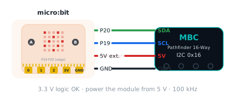
| Sensor | micro:bit |
|---|---|
| SDA | P20 |
| SCL | P19 |
| VCC | external 5 V (or try 3V) |
| GND | GND (the servo battery − goes here too) |
The values used on this page
"Left / right" always means sensor mounted on the robot, you standing behind it looking forward: line on the left = negative, channel 1 = far left.
| Block | JavaScript | Range | Meaning | Used in |
|---|---|---|---|---|
| line position | mbc.linePosition() |
−16~+16 | which channel the line is under, 0 = centre, negative = left | 1, 3, 4 |
| fine line position | mbc.linePositionFine() |
−100~+100 | finer version of the position, same sign | 5 |
| line is seen | mbc.lineSeen() |
true / false | at least one channel sees the line | 1, 3, 4, 5 |
| line width | mbc.lineWidth() |
0~16 | channels on the line, 0 = no line | 1 |
| last exit direction | mbc.lineLastDirection() |
−16~+16 | where the line was before it was lost, negative = left | 5 |
| on line lost / found / fork | mbc.onLineEvent(...) |
事件 | fires once when the segment count becomes 0 / >0 again / ≥2 | 2, 5 |
| calibrate auto (sweep for 5 s) | mbc.lineCalibrate(MbcLineCalib.Auto) |
命令 E7 | sweep over black line and white surface for 5 s, saved in the sensor | 2 |
| is calibrating / calibration count | mbc.lineCalibrating() / mbc.lineCalibrationCount() |
true / false、0~255 | calibrating flag (F3 b2) and calibrations since power-on | 2 |
| follow black / white line | mbc.lineSetColor(MbcLineColor.Black) |
命令 E0/E1 | black line on white (default) or white line on black | 2 |
| wait for device at … ready | mbc.waitReady(mbc.ADDR_LINE, 3000) |
true / false | waits up to 3 s, true when the sensor answers (Advanced → Device) | 1 |
Example 1: Where is the line
What this example does: A column of LEDs follows the line: line on the left, column on the left; line centred, column in the middle. Press A to show the line position number, B the line width. Use it to check the wiring and that left / right are not swapped.
What you need
- micro:bit V1 or V2 + USB cable
- Line Follower 16-ch (Universal I2C edition) + 4-pin cable
- a sheet of white paper with a strip of black electrical tape (about 2 cm wide)
Wiring: As in the wiring table above: SDA → P20, SCL → P19, VCC → 3V, GND → GND.
Download: ex01_show_position.ts (right-click, save) → MakeCode New Project → gear → Extensions → paste https://github.com/contactmbcrobot/pxt-mbc-sensors → switch to JavaScript (top) → select all, delete, paste the file → Download and drag the .hex onto the MICROBIT drive.
Code
// Line follower 16-ch × micro:bit example 1: where is the line (an LED column follows the line)
// What it does: slide the sensor across a black line and a column of LEDs follows it; press A to show the line position number, B to show the line width.
// Wiring: sensor SDA → P20, SCL → P19, VCC → 3V (or external 5 V), GND → GND.
// Setup: MakeCode new project → Extensions → paste https://github.com/contactmbcrobot/pxt-mbc-sensors → switch to JavaScript, paste this whole file → download to the micro:bit.
// You see: a tick at power-on (sensor found); line on the left → column on the left; centred → middle column; no line → an X.

const CH = 16                                              // channels: 8 on the 16-ch, 16 on the 16-ch
let busy = false                                          // pause the column while a button shows a number

if (mbc.waitReady(mbc.ADDR_LINE, 3000)) {                 // wait up to 3 s for the sensor to answer
    basic.showIcon(IconNames.Yes)
} else {
    basic.showIcon(IconNames.No)                          // no answer: check P19 / P20 and power
}

basic.forever(function () {
    if (busy) {
        basic.pause(100)
        return
    }
    if (mbc.lineSeen()) {
        let pos = mbc.linePosition()                      // −CH (far left) .. +CH (far right), 0 = centre
        let x = Math.round(Math.map(pos, -CH, CH, 0, 4))  // map to LED column 0..4
        basic.clearScreen()
        for (let y = 0; y < 5; y++) {
            led.plot(x, y)                                // draw the whole column
        }
    } else {
        basic.showIcon(IconNames.No, 0)                   // no line seen
    }
    basic.pause(50)
})

input.onButtonPressed(Button.A, function () {
    busy = true
    basic.showNumber(mbc.linePosition())                  // line position: negative = line on the left (seen from behind the robot)
    busy = false
})
input.onButtonPressed(Button.B, function () {
    busy = true
    basic.showNumber(mbc.lineWidth())                     // line width: channels on the line, 0 = no line
    busy = false
})
Step by step
const CH = 16: the channel count. On the 8-ch change it back to 8, nothing else.mbc.waitReady(mbc.ADDR_LINE, 3000): wait up to 3 s for the sensor to answer; tick if it does, X if not.basic.forever: repeat forever. First askmbc.lineSeen()"is a line seen"; if not, show an X.- Line seen:
mbc.linePosition()reads −16..+16,Math.mapturns it into LED column 0..4, and a loop ofled.plotlights all 5 LEDs of that column. - Buttons A / B:
basic.showNumberscrolls the number; thebusyvariable pauses the column meanwhile so the two do not fight over the screen.
What you should see
- Power-on: a tick (sensor found).
- Sensor on the paper with the line under its centre: middle column; A shows 0.
- Move the sensor right (the line is now on its left): the column moves left; A shows a negative number.
- Lift it off the paper: X.
FAQ
- The column moves the opposite way to the line? → The sensor is mounted backwards (channel 1 must be on the left of the robot). Turn the sensor 180°, do not change the code.
- The column never leaves the middle? → Not calibrated yet: run example 2 and press A for auto calibration, or every value is 0 (check whether example 1 showed the X).
- An X right at power-on (sensor not found)? → Check SDA = P20 and SCL = P19 are not swapped, that the external power is on, and with crocodile clips that no clip touches the neighbouring pad.
- All zeros in the simulator? → Normal. The MakeCode simulator has no real I2C, every read is 0; download to the micro:bit to see real values.
- No sound on a V1? → The V1 has no speaker; connect a buzzer or headphones between P0 and GND.
Example 2: Lost-line alarm + one-key calibration
What this example does: Line seen → happy face; line gone → sad face and a beep. Press A for the 5-second auto calibration (LED counts 5 4 3 2 1), B to switch black / white line mode. It uses the "event" blocks: they fire the moment the line is lost, instead of asking all the time.
What you need
- Everything from example 1
- On a V1 also a buzzer or headphones on P0
Wiring: Same as example 1.
Download: ex02_line_alarm.ts (right-click, save) → MakeCode New Project → gear → Extensions → paste https://github.com/contactmbcrobot/pxt-mbc-sensors → switch to JavaScript (top) → select all, delete, paste the file → Download and drag the .hex onto the MICROBIT drive.
Code
// Line follower 16-ch × micro:bit example 2: lost-line alarm + one-key calibration
// What it does: line seen → happy face; line lost → sad face and a beep. Press A for the 5-second auto calibration (LED countdown), B to switch black / white line.
// Wiring: sensor SDA → P20, SCL → P19, VCC → 3V (or external 5 V), GND → GND. On a V1 connect a buzzer or headphones to P0 for sound (V2 has a speaker).
// Setup: a sheet of white paper with a strip of black tape. Extension and paste steps as in example 1.
// You see: sensor over the line → happy; lifted away → sad + beep; press A → 5 4 3 2 1, the calibration count, then a tick.

let white = false                                         // white-line mode on?

mbc.lineSetColor(MbcLineColor.Black)                      // start in black-line mode (the default)
basic.showIcon(IconNames.Happy)

mbc.onLineEvent(MbcLineEvent.Lost, function () {          // fires once when the segment count drops to 0
    basic.showIcon(IconNames.Sad, 0)
    music.playTone(Note.C, music.beat(BeatFraction.Half)) // low C for half a beat
})
mbc.onLineEvent(MbcLineEvent.Found, function () {         // line found again
    basic.showIcon(IconNames.Happy, 0)
})

input.onButtonPressed(Button.A, function () {
    mbc.lineCalibrate(MbcLineCalib.Auto)                  // sweep the sensor over black line and white paper for 5 s
    for (let i = 5; i > 0; i--) {
        basic.showNumber(i)                               // countdown
        basic.pause(1000)
    }
    while (mbc.lineCalibrating()) {                       // wait until the calibrating flag clears
        basic.pause(100)
    }
    basic.showNumber(mbc.lineCalibrationCount())          // calibrations done since power-on
    basic.showIcon(IconNames.Yes)
})

input.onButtonPressed(Button.B, function () {
    white = !white
    mbc.lineSetColor(white ? MbcLineColor.White : MbcLineColor.Black)   // black line on white ↔ white line on black
    basic.showString(white ? "W" : "B")
})
Step by step
mbc.lineSetColor(MbcLineColor.Black): start in black-line mode (command E0).mbc.onLineEvent(MbcLineEvent.Lost, ...): runs once when the segment count drops from >0 to 0 → sad face +music.playTonefor half a beat.Foundis the line coming back → happy face.- Button A:
mbc.lineCalibrate(MbcLineCalib.Auto)sends command E7 and the sensor starts its 5-second calibration; aforloop counts down meanwhile. while (mbc.lineCalibrating()): while the calibrating flag (F3 b2) is still 1 wait another 0.1 s; continue when it clears.mbc.lineCalibrationCount(): shows how many calibrations finished since power-on, proving it really ran.- Button B: the
whitevariable flips andlineSetColorswitches between black (E0) and white (E1); the screen shows B or W.
What you should see
- Sensor over the line: happy. Lifted away: sad + one beep (only once, not continuous).
- Press A and sweep the sensor over black line and white paper a few times within 5 s → the count (1 the first time) → a tick. Positions are more accurate afterwards.
- Press B, W shows: now only a white line on black is treated as a line.
FAQ
- The count never shows after A? → The calibrating flag never clears, usually because the sensor is not connected (with all-zero reads
lineCalibrating()is false and it skips straight on). Run example 1 first and look for the tick. - No sound when the line is lost? → A V1 needs a buzzer; on a V2 make sure the speaker is not turned off in MakeCode.
Example 3: A steering servo follows the line
What this example does: A 9 g servo acts as a steering wheel: line on the left, the servo turns left, the further off-centre the bigger the turn (80° at the outermost channel); line lost, back to centre. The first example where the sensor moves something. Press A to show the angle.
What you need
- Everything from example 1, calibrated once with example 2
- one 9 g servo (SG90)
- a 4.8–6 V battery pack (4 × AA) and jumper wires
Wiring: Sensor as in example 1. Servo orange (signal) → P1, red → external 4.8–6 V battery +, brown → battery −, and run a second wire from battery − to micro:bit GND (common ground).
Download: ex03_steer_servo.ts (right-click, save) → MakeCode New Project → gear → Extensions → paste https://github.com/contactmbcrobot/pxt-mbc-sensors → switch to JavaScript (top) → select all, delete, paste the file → Download and drag the .hex onto the MICROBIT drive.
Code
// Line follower 16-ch × micro:bit example 3: a steering servo follows the line
// What it does: a 9 g servo (SG90) acts as a steering wheel: line on the left → servo turns left, further off-centre → bigger turn; line lost → back to centre. Press A to show the angle.
// Wiring: sensor SDA → P20, SCL → P19, VCC → 3V, GND → GND. Servo orange (signal) → P1, red → external 4.8–6 V battery +, brown → battery − joined to micro:bit GND (common ground).
// Setup: the black-line sheet from example 2, calibrated once.
// You see: move the sensor so the line is on its left → the servo arm swings one way; line on the right → the other way; lift it away → back to 90°.

const CH = 16                                              // channels: 8 on the 16-ch, 16 on the 16-ch
const GAIN = Math.idiv(80, CH)                            // degrees per channel: the outermost channel gives ±80°
let angle = 90

basic.forever(function () {
    if (mbc.lineSeen()) {
        angle = 90 + mbc.linePosition() * GAIN            // line on the left (negative) → angle below 90
    } else {
        angle = 90                                        // no line: centre
    }
    angle = Math.constrain(angle, 0, 180)
    pins.servoWritePin(AnalogPin.P1, angle)               // 0..180°
    basic.pause(30)
})

input.onButtonPressed(Button.A, function () {
    basic.showNumber(angle)
})
Step by step
GAIN = Math.idiv(80, CH): degrees per channel. 5° on the 16-ch, 10° on the 8-ch, so the outermost channel is 80° either way.- Line seen:
angle = 90 + position × GAIN; line on the left (negative) gives less than 90, on the right more than 90. - No line:
angle = 90, centre. Math.constrain(angle, 0, 180): a servo only goes 0..180°, clamp anything beyond.pins.servoWritePin(AnalogPin.P1, angle): send the angle to the servo on P1, every 30 ms.
What you should see
- Line centred: servo at 90°.
- Move the sensor right (line on its left): the arm swings one way, more the further off-centre.
- Lift it off: back to 90°. A shows 90.
FAQ
- The servo jitters or the micro:bit keeps resetting? → Never power the servo from the micro:bit 3V pin: use the battery pack, with battery − joined to micro:bit GND.
- It turns the wrong way? → Change
90 + ...to90 - ..., it depends on how the servo is mounted.
Example 4: Line-following car (three-way)
What this example does: Press A to drive: line on the left → turn left, on the right → turn right, centred → straight; line lost → stop. Press B to stop. Only three actions, the easiest line follower to understand.
What you need
- A two-wheel car: two continuous-rotation servos (e.g. FS90R) as wheels plus a caster
- the line follower at the front, 0.5–1 cm above the floor
- a 4.8–6 V battery pack
- a black-line track (white paper + black tape, no sharp bends)
Wiring: Sensor as in example 1, mounted at the front 0.5–1 cm above the floor. Left continuous-rotation servo signal → P1, right → P2; both servo red wires to the 4.8–6 V battery pack +, brown to battery −, and battery − also to micro:bit GND.
Download: ex04_simple_follow.ts (right-click, save) → MakeCode New Project → gear → Extensions → paste https://github.com/contactmbcrobot/pxt-mbc-sensors → switch to JavaScript (top) → select all, delete, paste the file → Download and drag the .hex onto the MICROBIT drive.
Code
// Line follower 16-ch × micro:bit example 4: line-following car (three-way)
// What it does: press A to drive: line on the left → turn left, on the right → turn right, centred → straight; line lost → stop. Press B to stop.
// Wiring: sensor SDA → P20, SCL → P19, VCC → 3V, GND → GND. Left continuous-rotation servo signal → P1, right → P2; both servos powered from a 4.8–6 V battery pack whose − is joined to micro:bit GND.
// Setup: a two-wheel car (two continuous-rotation servos as wheels), the sensor at the front 0.5–1 cm above the floor, a black-line track.
// You see: after A the arrow points up and the car follows the line; the arrow points the way it turns; off the line → sad face, stop.

let running = false

// left servo P1, right servo P2 (continuous rotation); left / right = −100..100, positive = forward
function drive(left: number, right: number): void {
    left = Math.constrain(left, -100, 100)
    right = Math.constrain(right, -100, 100)
    pins.servoWritePin(AnalogPin.P1, Math.round(90 + left * 0.9))    // 90 = stop, 180 = full forward, 0 = full reverse
    pins.servoWritePin(AnalogPin.P2, Math.round(90 - right * 0.9))   // the right servo is mounted mirrored, so subtract
}

input.onButtonPressed(Button.A, function () {
    running = true
    basic.showArrow(ArrowNames.North, 0)
})
input.onButtonPressed(Button.B, function () {
    running = false
    drive(0, 0)
    basic.showIcon(IconNames.No, 0)
})

basic.forever(function () {
    if (!running) {
        basic.pause(100)
        return
    }
    if (!mbc.lineSeen()) {
        drive(0, 0)                                       // stop when the line is lost
        basic.showIcon(IconNames.Sad, 0)
    } else {
        let pos = mbc.linePosition()                      // negative = line on the left
        if (pos < 0) {
            drive(20, 60)                                 // left slow, right fast = turn left
            basic.showArrow(ArrowNames.West, 0)
        } else if (pos > 0) {
            drive(60, 20)                                 // turn right
            basic.showArrow(ArrowNames.East, 0)
        } else {
            drive(50, 50)                                 // straight
            basic.showArrow(ArrowNames.North, 0)
        }
    }
    basic.pause(20)
})
Step by step
function drive(left, right): every driving example on this page uses it. Numbers −100..100, positive = forward. Left wheel90 + left × 0.9(90 stop, 180 full forward); the right servo is mounted mirrored, so90 − right × 0.9.- Button A:
running = true; button B:running = falseanddrive(0, 0). basic.forever: when not running do nothing (return).!mbc.lineSeen(): line lost → stop and sad face, so the car does not run off the track.pos < 0(line on the left) →drive(20, 60): left slow, right fast = turn left.pos > 0the other way.pos == 0→ both wheels equal, straight.
What you should see
- Press A: up arrow, the car follows the line; in bends the arrow points the way it turns.
- Lift the car: sad face, both wheels stop.
- Press B: X, stop.
FAQ
- The car reverses after A? → Both servos are mounted the other way: in
drivechange+ leftto- leftand- rightto+ right. Only one wheel wrong → change only that line. - The car wiggles along the line? → Change 60 / 20 to 50 / 30 (gentler turns), or use the proportional control of example 5.
- It never fully stops, the wheels creep? → "Stop" on a continuous-rotation servo is not always exactly 90: adjust the trim screw on the servo, or try 88..92 instead of 90.
Example 5: Smooth line following + stop at the 3rd crossing (all together)
What this example does: Proportional control on the fine position: the correction is as big as the error, so the car does not wiggle; crossings (fork event) are counted and the car stops at the 3rd; when the line is lost the car spins back using the last exit direction. Everything learned so far, reading values, events and driving, in one program.
What you need
- The car from example 4
- a black-line track with 3 crossings
Wiring: Same as example 4.
Download: ex05_smooth_follow_stop.ts (right-click, save) → MakeCode New Project → gear → Extensions → paste https://github.com/contactmbcrobot/pxt-mbc-sensors → switch to JavaScript (top) → select all, delete, paste the file → Download and drag the .hex onto the MICROBIT drive.
Code
// Line follower 16-ch × micro:bit example 5: smooth line following + stop at the 3rd crossing (all together)
// What it does: proportional control on the fine position, so the car steers smoothly; counts crossings and stops at the 3rd; when the line is lost it spins back using the last exit direction. A = start, B = stop.
// Wiring: as example 4 (sensor P19 / P20, left wheel P1, right wheel P2, servos on their own battery, common ground).
// Setup: a black-line track with 3 crossings.
// You see: after A the car follows smoothly, the LEDs show 1, 2, 3 at each crossing and the car stops with a tick at 3; lift the track away and the car turns toward where the line went, then carries on when it finds it.

const SPEED = 50
const KP = 0.5                                            // fine position ±100 → correction ±50
let running = false
let crossings = 0

// left servo P1, right servo P2 (continuous rotation); left / right = −100..100, positive = forward
function drive(left: number, right: number): void {
    left = Math.constrain(left, -100, 100)
    right = Math.constrain(right, -100, 100)
    pins.servoWritePin(AnalogPin.P1, Math.round(90 + left * 0.9))    // 90 = stop, 180 = full forward, 0 = full reverse
    pins.servoWritePin(AnalogPin.P2, Math.round(90 - right * 0.9))   // the right servo is mounted mirrored, so subtract
}

mbc.onLineEvent(MbcLineEvent.Fork, function () {          // segment count ≥ 2: crossing or fork
    if (!running) {
        return
    }
    crossings += 1
    basic.showNumber(crossings)
    if (crossings >= 3) {
        running = false
        drive(0, 0)
        basic.showIcon(IconNames.Yes)
    }
})
mbc.onLineEvent(MbcLineEvent.Lost, function () {
    if (!running) {
        return
    }
    if (mbc.lineLastDirection() < 0) {                    // the line left on the left → spin left to find it
        drive(-30, 30)
    } else {
        drive(30, -30)
    }
    basic.showIcon(IconNames.Confused, 0)
})

input.onButtonPressed(Button.A, function () {
    crossings = 0
    running = true
    basic.showArrow(ArrowNames.North, 0)
})
input.onButtonPressed(Button.B, function () {
    running = false
    drive(0, 0)
    basic.showIcon(IconNames.No, 0)
})

basic.forever(function () {
    if (running && mbc.lineSeen()) {
        let err = mbc.linePositionFine()                  // −100..+100, negative = line on the left
        let turn = err * KP                               // line on the left → negative turn → left wheel slows = turn left
        drive(SPEED + turn, SPEED - turn)
    }
    basic.pause(20)
})
Step by step
KP = 0.5: fine position −100..+100 × 0.5 = correction −50..+50. Bigger = sharper steering.basic.forever: while running and the line is seen,err = fine position,turn = err × KP,drive(SPEED + turn, SPEED − turn). Line on the left (negative) → left wheel slows, right speeds up = smooth left turn.onLineEvent(Fork): segment count ≥ 2 (a crossing) →crossings + 1shown on the LEDs; at 3running = false, stop, tick.onLineEvent(Lost):mbc.lineLastDirection() < 0means the line left on the left →drive(−30, 30)spin left; otherwise spin right. The forever loop leaves the motors alone while no line is seen, so it keeps spinning until the line is back.- A: reset the count and start; B: stop.
What you should see
- Press A: the car follows smoothly, steadier than example 4.
- Each crossing: the LEDs show 1, 2, 3; at 3 the car stops with a tick.
- Pull the track away from under the car: puzzled face, the car spins toward the side the line went; put it back and it carries on.
FAQ
- One crossing counted twice? → Too slow: the segment count bounced twice while crossing. Raise
SPEED, or addbasic.pause(500)inside the Fork handler so one crossing is not counted again. - The car still wiggles? → Lower
KPfrom 0.5 to 0.3; if it still does, changebasic.pause(20)to 10 (faster updates). - It spins forever looking for the line? → The line is too far away. It only spins, it does not move forward; to search in an arc change the Lost handler to something like
drive(10, 40).
Next steps
- Every block, value and hardware note: Line Follower 16-ch × micro:bit
- What each value id means: Reference
- Extension source and issues: https://github.com/contactmbcrobot/pxt-mbc-sensors