
Pathfinder 16-Way (Line16) × micro:bit × MakeCode
Interactive tutorialmicro:bit
First time? Try the interactive tutorial in your browser first, then follow the steps below with your hub.
This page covers MakeCode (blocks / JavaScript) only: how to set it up for the Pathfinder 16-Way (Line16) on BBC micro:bit V1 / V2, how to read every value, the commands it supports and examples. Use the switcher above to change product, host or software.
Which edition and how to connect
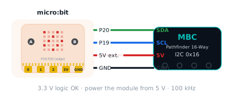
Get the Universal I2C edition and connect it to the I2C header of a micro:bit breakout (SDA = P20, SCL = P19), factory address 0x16. It draws little current, so VCC can go to the micro:bit 3V pin (about 90 mA on V1, 190 mA on V2); on batteries the rail can sag below 3 V, so switch to external 5 V if readings are unstable (share GND with the micro:bit).
Setup
What you need
- Sensor: Pathfinder 16-Way (Line16) (Universal I2C edition). SPIKE and EV3 editions run different firmware and cannot be read by a micro:bit.
- Board: BBC micro:bit V1 or V2, plus a breakout board or crocodile-clip adapter to reach P19 / P20.
- Software: MakeCode for micro:bit in the browser (makecode.microbit.org, blocks / JavaScript); the offline app (Windows / Mac) also works, but adding an extension the first time needs internet.
- Extension: pxt-mbc-sensors v2 (MIT, nothing to download, just paste the URL).
Important
Bench test pending: extension v2.0.5 compiles in MakeCode (V1 + V2) but has not yet been checked block by block on real hardware. Block names follow the GitHub release.
Install the software
- Open makecode.microbit.org → New Project.
- Traditional Chinese block names are included: switch the editor language (gearwheel → Language) if you prefer.
Make the software see the sensor
- Click Advanced → Extensions at the bottom of the toolbox (also in the gearwheel menu).
- Paste
https://github.com/contactmbcrobot/pxt-mbc-sensorsinto the search box and press Enter. - Click the mbc-sensors card. An "MBC Sensors" category appears with six groups: Line, Distance, Gamepad, IMU, Camera and Device.
- To use an example: switch to JavaScript at the top right → paste the example → download the
.hexand drag it onto the MICROBIT drive.
Tip
No approval, no download: teachers just hand the URL to students. To pin a version, paste
https://github.com/contactmbcrobot/pxt-mbc-sensors#v2.0.5.
Wiring
The micro:bit I2C pins are fixed: P19 = SCL, P20 = SDA (on the edge connector, so you need a breakout board or clip adapter). On the MBC 4-pin sensor cable TX goes to SCL and RX to SDA, exactly as when wiring to an Arduino.
| Sensor | micro:bit | Note |
|---|---|---|
| SCL (TX) | P19 | I2C clock |
| SDA (RX) | P20 | I2C data |
| VCC | 3V or external 5 V | power-hungry products must not draw from the micro:bit 3V pin |
| GND | GND | with external power, share GND with the micro:bit |
- 3V pin current: V1 about 90 mA, V2 about 190 mA; on batteries the rail can drop to just over 2 V. Ranger 8-way, Controller PS4 / PS5 and the SharpShot must use external 5 V; other products can try 3V first, with external 5 V recommended on batteries.
- Logic level: MBC product I2C lines are 3.3 V, compatible with the micro:bit without a level shifter.
- This product's factory address is
0x16; products with different addresses can share the same P19 / P20 bus.
Calibrate first (only once)
The Pathfinder has to "learn" the black and white of your mat before its numbers are right. Calibration is stored in the sensor and survives power-off (until you change mats).
- Plug in the sensor and turn the hub on (the sensor lights come on).
- Hold the calibration button for about 0.5 s, then release it (do not keep holding it; holding it keeps restarting calibration).
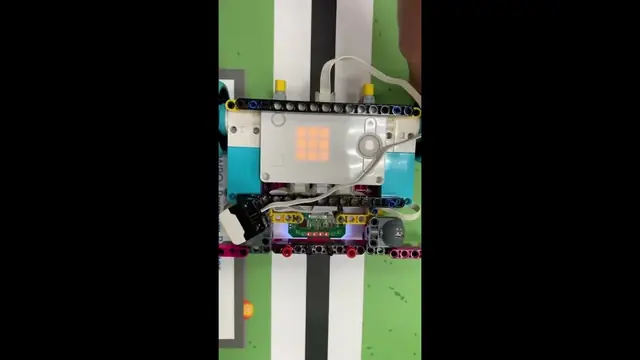
- When the green calibration LED (next to the button) lights up, sweep the sensor back and forth between the black line and the white floor within 5 seconds. All 16 sensing points must pass over the darkest black line and the brightest white area.
- Keep the sensor 3~12 mm above the surface while sweeping; higher reads poorly.
- The green LED goes off = calibration done, saved in the sensor automatically.
How do I know it worked? On the white floor the "line width" is 0; on a normal black line it is 3~5.
Tip
You can also calibrate with a block: "line follower calibrate …" with "as black" (E2), "as white" (E3) or "5-second sweep" (E7); the result is saved in the sensor.
First test
- Check the wiring first with the "Device → wait for device at 0x16 ready" or "device at 0x16 is ready" block.
- Download the
.hexof example 1 on this page to the micro:bit. - If the number on the LEDs changes with what is in front of the sensor, everything is connected.
FAQ
- Values are always 0? With no device connected the reporter blocks return 0 (the internal −32768 is filtered), every yes / no block returns false, and nothing throws. Check in order: wiring (SDA = P20, SCL = P19) → external power on → "device at … is ready" is true.
- On a V1, the compass and accelerometer stop working too? On V1 the external I2C bus is shared with the onboard accelerometer, so a sensor holding SDA low also kills them. V2 has a separate external bus.
- Works on and off? STM32 products (Pathfinder, Ranger, PS2, IMU) clock-stretch, and the nRF52 on the V2 has a known clock-stretching issue (errata 219), so V1 and V2 both need a bench test. ESP32 products (PS4, SharpShot) do not stretch; the extension already waits 2 ms after writing the value id.
- Two products of the same kind? They share an address: first change one with "Device → change device at … to address …" (applied after reboot), then tell the extension with that product's "use address" block.
Reading values
After adding pxt-mbc-sensors, find the blocks in the MBC Sensors category; the JavaScript form is shown too, address 0x16.
line position linePos
| Range | Meaning |
|---|---|
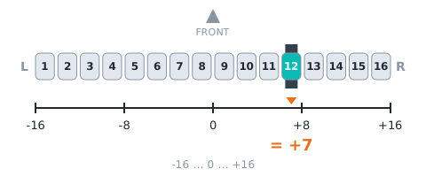
-16~+16 |
which channel the line is under: −16 (far left) to +16 (far right), 0 = centre; seen from behind the robot, negative = left (normally ±15; ±16 only for 200 ms after the line leaves the outermost channel) |
(line position :: #00A4E4)
let linePos = mbc.linePosition() // line position:-16~+16Returns 0 when the sensor does not answer; check with "device at … is ready" first.
fine position linePosFine
| Range | Meaning |
|---|---|
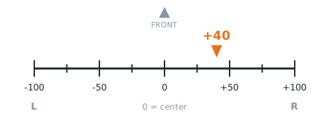
-100~+100 |
sub-channel position: −100 to +100, 0 = centre, negative = left (same sign as line position) |
(fine line position :: #00A4E4)
let linePosFine = mbc.linePositionFine() // fine position:-100~+100Returns 0 when the sensor does not answer; check with "device at … is ready" first.
line width lineWidth
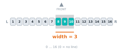
| Range | Meaning |
|---|---|
0~16 路 |
number of channels on the line, 0~16; 0 = no line |
(line width :: #00A4E4)
let lineWidth = mbc.lineWidth() // line width:0~16 路Returns 0 when the sensor does not answer; check with "device at … is ready" first.
line segments groupCount
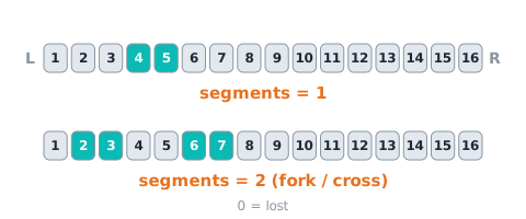
| Range | Meaning |
|---|---|
0~8 |
number of separate line segments: 0 = lost, 1 = one line, ≥2 = fork / crossing |
(line segments :: #00A4E4)
let groupCount = mbc.lineSegments() // line segments:0~8Related block "line is seen"
let lineSeen = mbc.lineSeen()Related block "on line [lost]"
mbc.onLineEvent(MbcLineEvent.Lost, function () {
})
Returns 0 when the sensor does not answer; check with "device at … is ready" first.
line bitmap bitmap
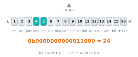
| Range | Meaning |
|---|---|
0~65535 bit |
bit0 = channel 1 (left) … bit15 = channel 16; 1 = that channel sees the line |
(line bitmap :: #00A4E4)
let bitmap = mbc.lineBitmap() // line bitmap:0~65535 bitRelated block "channel 1 is on the line"
let lineChannelOnLine = mbc.lineChannelOnLine(1)Returns 0 when the sensor does not answer; check with "device at … is ready" first.
last exit direction lastDir
| Range | Meaning |
|---|---|
-16~+16 |
where the line was before it was lost: −16 to +16 (negative = left); keeps the last value |
(last exit direction :: #00A4E4)
let lastDir = mbc.lineLastDirection() // last exit direction:-16~+16Returns 0 when the sensor does not answer; check with "device at … is ready" first.
threshold threshold
| Range | Meaning |
|---|---|
1~99 |
reflect threshold for 'on line', 1~99, default 40 (firmware shipped before 2026-11-03: 50); set with E4 |
(line threshold :: #00A4E4)
let threshold = mbc.lineThreshold() // threshold:1~99Returns 0 when the sensor does not answer; check with "device at … is ready" first.
calibrations done calibCount
| Range | Meaning |
|---|---|
0~255 次 |
number of calibrations completed since power-on (button calibrations included) |
(line calibration count :: #00A4E4)
let calibCount = mbc.lineCalibrationCount() // calibrations done:0~255 次Related block "line follower is calibrating"
let lineCalibrating = mbc.lineCalibrating()Returns 0 when the sensor does not answer; check with "device at … is ready" first.
channel 1~16 reflect light
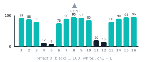
| Range | Meaning |
|---|---|
0~100 |
calibrated reflect of channel 1 |
(channel (1) reflect :: #00A4E4)
let light = mbc.lineChannel(1) // channel 1~16 reflect:0~100 (N = 1~16)Returns 0 when the sensor does not answer; check with "device at … is ready" first.
Commands
black line mode blackLine
follow a black line (default); RAM only, back to the default after reset
line follower follow [black v] line :: #00A4E4
mbc.lineSetColor(MbcLineColor.Black) // black line modewhite line mode whiteLine
follow a white line (F3 b1 = 1); RAM only, back to the default after reset
line follower follow [white v] line :: #00A4E4
mbc.lineSetColor(MbcLineColor.White) // white line modecalibrate black calibBlack
store the current reading as black (sensor over the black line), ~50 ms; saved to EEPROM
line follower calibrate [current reading is black v] :: #00A4E4
mbc.lineCalibrate(MbcLineCalib.Black) // calibrate blackcalibrate white calibWhite
store the current reading as white (sensor over the white surface), ~50 ms; saved to EEPROM
line follower calibrate [current reading is white v] :: #00A4E4
mbc.lineCalibrate(MbcLineCalib.White) // calibrate whiteset threshold setThreshold
threshold 1~99 (RAM only, back to 40 after reboot); on SPIKE an out-of-range value returns failed (state 2)
line follower set threshold (50) :: #00A4E4
mbc.lineSetThreshold(50) // set threshold5-second auto calibration calibAuto
sweep the sensor across black line and white surface for 5 s; min/max become the references; F3 b2 = 1 meanwhile
line follower calibrate [auto \(sweep for 5 s\) v] :: #00A4E4
mbc.lineCalibrate(MbcLineCalib.Auto) // 5-second auto calibrationmirror left/right reverse
[0 normal / 1 mirrored]: for a sensor mounted backwards — channel order and line position are mirrored; calibration stays per physical channel; RAM only, 0 after reset (not in legacy mBlock); on SPIKE an out-of-range value returns failed (state 2)
No dedicated block; in JavaScript use mbc.writeCmd(0x16, 0xE9, [params]).
Examples
This page is for people who have never written code. The 5 examples start with "show a value on the LEDs" and build up to "drive a car". Everything is written for the MakeCode web editor with the MBC extension pxt-mbc-sensors v2: switch to JavaScript, paste an example and it runs; switch back to Blocks to see which blocks it becomes.
Important
- Extension pxt-mbc-sensors v2 has not been verified on hardware yet. Every example on this page compiles with the MakeCode CLI (once for V1, once for V2); value directions, ready times and power are still to be confirmed on a real board, see "to be tested" in the hardware checklist below.
- Use the Universal I2C edition of the product. The SPIKE and EV3 editions have different firmware and cannot be read by a micro:bit.
Software
| Editor | micro:bit V1 | micro:bit V2 | How |
|---|---|---|---|
| MakeCode web editor (makecode.microbit.org, Blocks / JavaScript) | ✔ (less memory, but every example here fits) | ✔ | New Project → gear → Extensions → paste https://github.com/contactmbcrobot/pxt-mbc-sensors → switch to JavaScript (top) → paste the example → Download the .hex and drag it onto the MICROBIT drive |
| MakeCode offline app (Windows / Mac) | ✔ | ✔ | Same; adding the extension the first time needs internet |
| Python Editor (MicroPython) | — | — | no MBC module yet |
- Sound: V2 has a built-in speaker; a V1 needs a buzzer or headphones on P0.
- Servos / motors: the examples use
pins.servoWritePin: one 9 g servo (SG90) on P1; for driving, two continuous-rotation servos (e.g. FS90R), left wheel P1, right wheel P2. Always power servos from an external 4.8–6 V battery pack whose − is joined to the micro:bit GND (common ground); never drive servos from the micro:bit 3V pin. - Block names: with the editor language set to English the blocks read as in the tables below; the tables also give the JavaScript call.
Before you start: hardware checklist (to be tested)
The micro:bit is a 3.3 V board. Each check must pass before an MBC product is connected; "to be tested" marks items extension v2 has not yet confirmed on real hardware.
| Check | This product | Status |
|---|---|---|
| Voltage | MBC products use 3.3 V I2C levels: connect straight to P19 / P20, no level shifter | ✔ |
| Power | about 45 mA for 16 channels; external 5 V recommended, the micro:bit 3V pin (limit about 90 mA on V1, 190 mA on V2) must be tested | to be tested |
| I2C pull-ups | the micro:bit already has 4.7 kΩ; if the product also has pull-ups, check the low level stays ≤ 0.3×VDD | to be tested |
| Clock stretching | the STM32 slave stretches the clock by default; the V2 (nRF52833) has a known issue with stretching, test on V1 and V2 | to be tested |
| Address clash | factory address 0x16, the same as the 8-ch; to connect an 8-ch and a 16-ch together change one address first | — |
| Ready time | ready immediately after power-on (F3 b0 is always 1) | to be tested |
If you read nothing: check the wiring (SDA = P20, SCL = P19) → the external power → whether the "device at … is ready" block (Device group, advanced) returns true.
Wiring (the same for every example)
| Sensor | micro:bit |
|---|---|
| SDA | P20 |
| SCL | P19 |
| VCC | external 5 V (or try 3V) |
| GND | GND (the servo battery − goes here too) |
The values used on this page
"Left / right" always means sensor mounted on the robot, you standing behind it looking forward: line on the left = negative, channel 1 = far left.
| Block | JavaScript | Range | Meaning | Used in |
|---|---|---|---|---|
| line position | mbc.linePosition() |
−16~+16 | which channel the line is under, 0 = centre, negative = left | 1, 3, 4 |
| fine line position | mbc.linePositionFine() |
−100~+100 | finer version of the position, same sign | 5 |
| line is seen | mbc.lineSeen() |
true / false | at least one channel sees the line | 1, 3, 4, 5 |
| line width | mbc.lineWidth() |
0~16 | channels on the line, 0 = no line | 1 |
| last exit direction | mbc.lineLastDirection() |
−16~+16 | where the line was before it was lost, negative = left | 5 |
| on line lost / found / fork | mbc.onLineEvent(...) |
事件 | fires once when the segment count becomes 0 / >0 again / ≥2 | 2, 5 |
| calibrate auto (sweep for 5 s) | mbc.lineCalibrate(MbcLineCalib.Auto) |
命令 E7 | sweep over black line and white surface for 5 s, saved in the sensor | 2 |
| is calibrating / calibration count | mbc.lineCalibrating() / mbc.lineCalibrationCount() |
true / false、0~255 | calibrating flag (F3 b2) and calibrations since power-on | 2 |
| follow black / white line | mbc.lineSetColor(MbcLineColor.Black) |
命令 E0/E1 | black line on white (default) or white line on black | 2 |
| wait for device at … ready | mbc.waitReady(mbc.ADDR_LINE, 3000) |
true / false | waits up to 3 s, true when the sensor answers (Advanced → Device) | 1 |
Example 1: Where is the line
What this example does: A column of LEDs follows the line: line on the left, column on the left; line centred, column in the middle. Press A to show the line position number, B the line width. Use it to check the wiring and that left / right are not swapped.
What you need
- micro:bit V1 or V2 + USB cable
- Line Follower 16-ch (Universal I2C edition) + 4-pin cable
- a sheet of white paper with a strip of black electrical tape (about 2 cm wide)
Wiring: As in the wiring table above: SDA → P20, SCL → P19, VCC → 3V, GND → GND.
Download: ex01_show_position.ts (right-click, save) → MakeCode New Project → gear → Extensions → paste https://github.com/contactmbcrobot/pxt-mbc-sensors → switch to JavaScript (top) → select all, delete, paste the file → Download and drag the .hex onto the MICROBIT drive.
Code
// Line follower 16-ch × micro:bit example 1: where is the line (an LED column follows the line)
// What it does: slide the sensor across a black line and a column of LEDs follows it; press A to show the line position number, B to show the line width.
// Wiring: sensor SDA → P20, SCL → P19, VCC → 3V (or external 5 V), GND → GND.
// Setup: MakeCode new project → Extensions → paste https://github.com/contactmbcrobot/pxt-mbc-sensors → switch to JavaScript, paste this whole file → download to the micro:bit.
// You see: a tick at power-on (sensor found); line on the left → column on the left; centred → middle column; no line → an X.

const CH = 16                                              // channels: 8 on the 16-ch, 16 on the 16-ch
let busy = false                                          // pause the column while a button shows a number

if (mbc.waitReady(mbc.ADDR_LINE, 3000)) {                 // wait up to 3 s for the sensor to answer
    basic.showIcon(IconNames.Yes)
} else {
    basic.showIcon(IconNames.No)                          // no answer: check P19 / P20 and power
}

basic.forever(function () {
    if (busy) {
        basic.pause(100)
        return
    }
    if (mbc.lineSeen()) {
        let pos = mbc.linePosition()                      // −CH (far left) .. +CH (far right), 0 = centre
        let x = Math.round(Math.map(pos, -CH, CH, 0, 4))  // map to LED column 0..4
        basic.clearScreen()
        for (let y = 0; y < 5; y++) {
            led.plot(x, y)                                // draw the whole column
        }
    } else {
        basic.showIcon(IconNames.No, 0)                   // no line seen
    }
    basic.pause(50)
})

input.onButtonPressed(Button.A, function () {
    busy = true
    basic.showNumber(mbc.linePosition())                  // line position: negative = line on the left (seen from behind the robot)
    busy = false
})
input.onButtonPressed(Button.B, function () {
    busy = true
    basic.showNumber(mbc.lineWidth())                     // line width: channels on the line, 0 = no line
    busy = false
})
Step by step
const CH = 16: the channel count. On the 8-ch change it back to 8, nothing else.mbc.waitReady(mbc.ADDR_LINE, 3000): wait up to 3 s for the sensor to answer; tick if it does, X if not.basic.forever: repeat forever. First askmbc.lineSeen()"is a line seen"; if not, show an X.- Line seen:
mbc.linePosition()reads −16..+16,Math.mapturns it into LED column 0..4, and a loop ofled.plotlights all 5 LEDs of that column. - Buttons A / B:
basic.showNumberscrolls the number; thebusyvariable pauses the column meanwhile so the two do not fight over the screen.
What you should see
- Power-on: a tick (sensor found).
- Sensor on the paper with the line under its centre: middle column; A shows 0.
- Move the sensor right (the line is now on its left): the column moves left; A shows a negative number.
- Lift it off the paper: X.
FAQ
- The column moves the opposite way to the line? → The sensor is mounted backwards (channel 1 must be on the left of the robot). Turn the sensor 180°, do not change the code.
- The column never leaves the middle? → Not calibrated yet: run example 2 and press A for auto calibration, or every value is 0 (check whether example 1 showed the X).
- An X right at power-on (sensor not found)? → Check SDA = P20 and SCL = P19 are not swapped, that the external power is on, and with crocodile clips that no clip touches the neighbouring pad.
- All zeros in the simulator? → Normal. The MakeCode simulator has no real I2C, every read is 0; download to the micro:bit to see real values.
- No sound on a V1? → The V1 has no speaker; connect a buzzer or headphones between P0 and GND.
Example 2: Lost-line alarm + one-key calibration
What this example does: Line seen → happy face; line gone → sad face and a beep. Press A for the 5-second auto calibration (LED counts 5 4 3 2 1), B to switch black / white line mode. It uses the "event" blocks: they fire the moment the line is lost, instead of asking all the time.
What you need
- Everything from example 1
- On a V1 also a buzzer or headphones on P0
Wiring: Same as example 1.
Download: ex02_line_alarm.ts (right-click, save) → MakeCode New Project → gear → Extensions → paste https://github.com/contactmbcrobot/pxt-mbc-sensors → switch to JavaScript (top) → select all, delete, paste the file → Download and drag the .hex onto the MICROBIT drive.
Code
// Line follower 16-ch × micro:bit example 2: lost-line alarm + one-key calibration
// What it does: line seen → happy face; line lost → sad face and a beep. Press A for the 5-second auto calibration (LED countdown), B to switch black / white line.
// Wiring: sensor SDA → P20, SCL → P19, VCC → 3V (or external 5 V), GND → GND. On a V1 connect a buzzer or headphones to P0 for sound (V2 has a speaker).
// Setup: a sheet of white paper with a strip of black tape. Extension and paste steps as in example 1.
// You see: sensor over the line → happy; lifted away → sad + beep; press A → 5 4 3 2 1, the calibration count, then a tick.

let white = false                                         // white-line mode on?

mbc.lineSetColor(MbcLineColor.Black)                      // start in black-line mode (the default)
basic.showIcon(IconNames.Happy)

mbc.onLineEvent(MbcLineEvent.Lost, function () {          // fires once when the segment count drops to 0
    basic.showIcon(IconNames.Sad, 0)
    music.playTone(Note.C, music.beat(BeatFraction.Half)) // low C for half a beat
})
mbc.onLineEvent(MbcLineEvent.Found, function () {         // line found again
    basic.showIcon(IconNames.Happy, 0)
})

input.onButtonPressed(Button.A, function () {
    mbc.lineCalibrate(MbcLineCalib.Auto)                  // sweep the sensor over black line and white paper for 5 s
    for (let i = 5; i > 0; i--) {
        basic.showNumber(i)                               // countdown
        basic.pause(1000)
    }
    while (mbc.lineCalibrating()) {                       // wait until the calibrating flag clears
        basic.pause(100)
    }
    basic.showNumber(mbc.lineCalibrationCount())          // calibrations done since power-on
    basic.showIcon(IconNames.Yes)
})

input.onButtonPressed(Button.B, function () {
    white = !white
    mbc.lineSetColor(white ? MbcLineColor.White : MbcLineColor.Black)   // black line on white ↔ white line on black
    basic.showString(white ? "W" : "B")
})
Step by step
mbc.lineSetColor(MbcLineColor.Black): start in black-line mode (command E0).mbc.onLineEvent(MbcLineEvent.Lost, ...): runs once when the segment count drops from >0 to 0 → sad face +music.playTonefor half a beat.Foundis the line coming back → happy face.- Button A:
mbc.lineCalibrate(MbcLineCalib.Auto)sends command E7 and the sensor starts its 5-second calibration; aforloop counts down meanwhile. while (mbc.lineCalibrating()): while the calibrating flag (F3 b2) is still 1 wait another 0.1 s; continue when it clears.mbc.lineCalibrationCount(): shows how many calibrations finished since power-on, proving it really ran.- Button B: the
whitevariable flips andlineSetColorswitches between black (E0) and white (E1); the screen shows B or W.
What you should see
- Sensor over the line: happy. Lifted away: sad + one beep (only once, not continuous).
- Press A and sweep the sensor over black line and white paper a few times within 5 s → the count (1 the first time) → a tick. Positions are more accurate afterwards.
- Press B, W shows: now only a white line on black is treated as a line.
FAQ
- The count never shows after A? → The calibrating flag never clears, usually because the sensor is not connected (with all-zero reads
lineCalibrating()is false and it skips straight on). Run example 1 first and look for the tick. - No sound when the line is lost? → A V1 needs a buzzer; on a V2 make sure the speaker is not turned off in MakeCode.
Example 3: A steering servo follows the line
What this example does: A 9 g servo acts as a steering wheel: line on the left, the servo turns left, the further off-centre the bigger the turn (80° at the outermost channel); line lost, back to centre. The first example where the sensor moves something. Press A to show the angle.
What you need
- Everything from example 1, calibrated once with example 2
- one 9 g servo (SG90)
- a 4.8–6 V battery pack (4 × AA) and jumper wires
Wiring: Sensor as in example 1. Servo orange (signal) → P1, red → external 4.8–6 V battery +, brown → battery −, and run a second wire from battery − to micro:bit GND (common ground).
Download: ex03_steer_servo.ts (right-click, save) → MakeCode New Project → gear → Extensions → paste https://github.com/contactmbcrobot/pxt-mbc-sensors → switch to JavaScript (top) → select all, delete, paste the file → Download and drag the .hex onto the MICROBIT drive.
Code
// Line follower 16-ch × micro:bit example 3: a steering servo follows the line
// What it does: a 9 g servo (SG90) acts as a steering wheel: line on the left → servo turns left, further off-centre → bigger turn; line lost → back to centre. Press A to show the angle.
// Wiring: sensor SDA → P20, SCL → P19, VCC → 3V, GND → GND. Servo orange (signal) → P1, red → external 4.8–6 V battery +, brown → battery − joined to micro:bit GND (common ground).
// Setup: the black-line sheet from example 2, calibrated once.
// You see: move the sensor so the line is on its left → the servo arm swings one way; line on the right → the other way; lift it away → back to 90°.

const CH = 16                                              // channels: 8 on the 16-ch, 16 on the 16-ch
const GAIN = Math.idiv(80, CH)                            // degrees per channel: the outermost channel gives ±80°
let angle = 90

basic.forever(function () {
    if (mbc.lineSeen()) {
        angle = 90 + mbc.linePosition() * GAIN            // line on the left (negative) → angle below 90
    } else {
        angle = 90                                        // no line: centre
    }
    angle = Math.constrain(angle, 0, 180)
    pins.servoWritePin(AnalogPin.P1, angle)               // 0..180°
    basic.pause(30)
})

input.onButtonPressed(Button.A, function () {
    basic.showNumber(angle)
})
Step by step
GAIN = Math.idiv(80, CH): degrees per channel. 5° on the 16-ch, 10° on the 8-ch, so the outermost channel is 80° either way.- Line seen:
angle = 90 + position × GAIN; line on the left (negative) gives less than 90, on the right more than 90. - No line:
angle = 90, centre. Math.constrain(angle, 0, 180): a servo only goes 0..180°, clamp anything beyond.pins.servoWritePin(AnalogPin.P1, angle): send the angle to the servo on P1, every 30 ms.
What you should see
- Line centred: servo at 90°.
- Move the sensor right (line on its left): the arm swings one way, more the further off-centre.
- Lift it off: back to 90°. A shows 90.
FAQ
- The servo jitters or the micro:bit keeps resetting? → Never power the servo from the micro:bit 3V pin: use the battery pack, with battery − joined to micro:bit GND.
- It turns the wrong way? → Change
90 + ...to90 - ..., it depends on how the servo is mounted.
Example 4: Line-following car (three-way)
What this example does: Press A to drive: line on the left → turn left, on the right → turn right, centred → straight; line lost → stop. Press B to stop. Only three actions, the easiest line follower to understand.
What you need
- A two-wheel car: two continuous-rotation servos (e.g. FS90R) as wheels plus a caster
- the line follower at the front, 0.5–1 cm above the floor
- a 4.8–6 V battery pack
- a black-line track (white paper + black tape, no sharp bends)
Wiring: Sensor as in example 1, mounted at the front 0.5–1 cm above the floor. Left continuous-rotation servo signal → P1, right → P2; both servo red wires to the 4.8–6 V battery pack +, brown to battery −, and battery − also to micro:bit GND.
Download: ex04_simple_follow.ts (right-click, save) → MakeCode New Project → gear → Extensions → paste https://github.com/contactmbcrobot/pxt-mbc-sensors → switch to JavaScript (top) → select all, delete, paste the file → Download and drag the .hex onto the MICROBIT drive.
Code
// Line follower 16-ch × micro:bit example 4: line-following car (three-way)
// What it does: press A to drive: line on the left → turn left, on the right → turn right, centred → straight; line lost → stop. Press B to stop.
// Wiring: sensor SDA → P20, SCL → P19, VCC → 3V, GND → GND. Left continuous-rotation servo signal → P1, right → P2; both servos powered from a 4.8–6 V battery pack whose − is joined to micro:bit GND.
// Setup: a two-wheel car (two continuous-rotation servos as wheels), the sensor at the front 0.5–1 cm above the floor, a black-line track.
// You see: after A the arrow points up and the car follows the line; the arrow points the way it turns; off the line → sad face, stop.

let running = false

// left servo P1, right servo P2 (continuous rotation); left / right = −100..100, positive = forward
function drive(left: number, right: number): void {
    left = Math.constrain(left, -100, 100)
    right = Math.constrain(right, -100, 100)
    pins.servoWritePin(AnalogPin.P1, Math.round(90 + left * 0.9))    // 90 = stop, 180 = full forward, 0 = full reverse
    pins.servoWritePin(AnalogPin.P2, Math.round(90 - right * 0.9))   // the right servo is mounted mirrored, so subtract
}

input.onButtonPressed(Button.A, function () {
    running = true
    basic.showArrow(ArrowNames.North, 0)
})
input.onButtonPressed(Button.B, function () {
    running = false
    drive(0, 0)
    basic.showIcon(IconNames.No, 0)
})

basic.forever(function () {
    if (!running) {
        basic.pause(100)
        return
    }
    if (!mbc.lineSeen()) {
        drive(0, 0)                                       // stop when the line is lost
        basic.showIcon(IconNames.Sad, 0)
    } else {
        let pos = mbc.linePosition()                      // negative = line on the left
        if (pos < 0) {
            drive(20, 60)                                 // left slow, right fast = turn left
            basic.showArrow(ArrowNames.West, 0)
        } else if (pos > 0) {
            drive(60, 20)                                 // turn right
            basic.showArrow(ArrowNames.East, 0)
        } else {
            drive(50, 50)                                 // straight
            basic.showArrow(ArrowNames.North, 0)
        }
    }
    basic.pause(20)
})
Step by step
function drive(left, right): every driving example on this page uses it. Numbers −100..100, positive = forward. Left wheel90 + left × 0.9(90 stop, 180 full forward); the right servo is mounted mirrored, so90 − right × 0.9.- Button A:
running = true; button B:running = falseanddrive(0, 0). basic.forever: when not running do nothing (return).!mbc.lineSeen(): line lost → stop and sad face, so the car does not run off the track.pos < 0(line on the left) →drive(20, 60): left slow, right fast = turn left.pos > 0the other way.pos == 0→ both wheels equal, straight.
What you should see
- Press A: up arrow, the car follows the line; in bends the arrow points the way it turns.
- Lift the car: sad face, both wheels stop.
- Press B: X, stop.
FAQ
- The car reverses after A? → Both servos are mounted the other way: in
drivechange+ leftto- leftand- rightto+ right. Only one wheel wrong → change only that line. - The car wiggles along the line? → Change 60 / 20 to 50 / 30 (gentler turns), or use the proportional control of example 5.
- It never fully stops, the wheels creep? → "Stop" on a continuous-rotation servo is not always exactly 90: adjust the trim screw on the servo, or try 88..92 instead of 90.
Example 5: Smooth line following + stop at the 3rd crossing (all together)
What this example does: Proportional control on the fine position: the correction is as big as the error, so the car does not wiggle; crossings (fork event) are counted and the car stops at the 3rd; when the line is lost the car spins back using the last exit direction. Everything learned so far, reading values, events and driving, in one program.
What you need
- The car from example 4
- a black-line track with 3 crossings
Wiring: Same as example 4.
Download: ex05_smooth_follow_stop.ts (right-click, save) → MakeCode New Project → gear → Extensions → paste https://github.com/contactmbcrobot/pxt-mbc-sensors → switch to JavaScript (top) → select all, delete, paste the file → Download and drag the .hex onto the MICROBIT drive.
Code
// Line follower 16-ch × micro:bit example 5: smooth line following + stop at the 3rd crossing (all together)
// What it does: proportional control on the fine position, so the car steers smoothly; counts crossings and stops at the 3rd; when the line is lost it spins back using the last exit direction. A = start, B = stop.
// Wiring: as example 4 (sensor P19 / P20, left wheel P1, right wheel P2, servos on their own battery, common ground).
// Setup: a black-line track with 3 crossings.
// You see: after A the car follows smoothly, the LEDs show 1, 2, 3 at each crossing and the car stops with a tick at 3; lift the track away and the car turns toward where the line went, then carries on when it finds it.

const SPEED = 50
const KP = 0.5                                            // fine position ±100 → correction ±50
let running = false
let crossings = 0

// left servo P1, right servo P2 (continuous rotation); left / right = −100..100, positive = forward
function drive(left: number, right: number): void {
    left = Math.constrain(left, -100, 100)
    right = Math.constrain(right, -100, 100)
    pins.servoWritePin(AnalogPin.P1, Math.round(90 + left * 0.9))    // 90 = stop, 180 = full forward, 0 = full reverse
    pins.servoWritePin(AnalogPin.P2, Math.round(90 - right * 0.9))   // the right servo is mounted mirrored, so subtract
}

mbc.onLineEvent(MbcLineEvent.Fork, function () {          // segment count ≥ 2: crossing or fork
    if (!running) {
        return
    }
    crossings += 1
    basic.showNumber(crossings)
    if (crossings >= 3) {
        running = false
        drive(0, 0)
        basic.showIcon(IconNames.Yes)
    }
})
mbc.onLineEvent(MbcLineEvent.Lost, function () {
    if (!running) {
        return
    }
    if (mbc.lineLastDirection() < 0) {                    // the line left on the left → spin left to find it
        drive(-30, 30)
    } else {
        drive(30, -30)
    }
    basic.showIcon(IconNames.Confused, 0)
})

input.onButtonPressed(Button.A, function () {
    crossings = 0
    running = true
    basic.showArrow(ArrowNames.North, 0)
})
input.onButtonPressed(Button.B, function () {
    running = false
    drive(0, 0)
    basic.showIcon(IconNames.No, 0)
})

basic.forever(function () {
    if (running && mbc.lineSeen()) {
        let err = mbc.linePositionFine()                  // −100..+100, negative = line on the left
        let turn = err * KP                               // line on the left → negative turn → left wheel slows = turn left
        drive(SPEED + turn, SPEED - turn)
    }
    basic.pause(20)
})
Step by step
KP = 0.5: fine position −100..+100 × 0.5 = correction −50..+50. Bigger = sharper steering.basic.forever: while running and the line is seen,err = fine position,turn = err × KP,drive(SPEED + turn, SPEED − turn). Line on the left (negative) → left wheel slows, right speeds up = smooth left turn.onLineEvent(Fork): segment count ≥ 2 (a crossing) →crossings + 1shown on the LEDs; at 3running = false, stop, tick.onLineEvent(Lost):mbc.lineLastDirection() < 0means the line left on the left →drive(−30, 30)spin left; otherwise spin right. The forever loop leaves the motors alone while no line is seen, so it keeps spinning until the line is back.- A: reset the count and start; B: stop.
What you should see
- Press A: the car follows smoothly, steadier than example 4.
- Each crossing: the LEDs show 1, 2, 3; at 3 the car stops with a tick.
- Pull the track away from under the car: puzzled face, the car spins toward the side the line went; put it back and it carries on.
FAQ
- One crossing counted twice? → Too slow: the segment count bounced twice while crossing. Raise
SPEED, or addbasic.pause(500)inside the Fork handler so one crossing is not counted again. - The car still wiggles? → Lower
KPfrom 0.5 to 0.3; if it still does, changebasic.pause(20)to 10 (faster updates). - It spins forever looking for the line? → The line is too far away. It only spins, it does not move forward; to search in an arc change the Lost handler to something like
drive(10, 40).
Next steps
- Every block, value and hardware note: Line Follower 16-ch × micro:bit
- What each value id means: Reference
- Extension source and issues: https://github.com/contactmbcrobot/pxt-mbc-sensors
More questions
- Cannot find the MBC blocks? In MakeCode Extensions, paste https://github.com/contactmbcrobot/pxt-mbc-sensors.
Still stuck? Contact us with your software and a screenshot of the program.
Downloads
- MakeCode extension pxt-mbc-sensors (paste this URL in MakeCode Extensions)
- Download centre (libraries, firmware, catalogue for every product)
Sources
- Host and software list:
_build/guides.json - Values and commands:
_build/protocol/line16.json(single source of truth) - Setup:
_build/guides/software/microbit-makecode.en.md、_build/guides/product/line16/microbit-makecode.en.md - Examples:
sensors/line16/microbit-examples.md