
Pathfinder 16-Way (Line16) × mBlock × mBlock 5
Interactive tutorialmBlock
First time? Try the interactive tutorial in your browser first, then follow the steps below with your hub.
This page covers mBlock 5 (MBC Pro Sensors extension) only: how to set it up for the Pathfinder 16-Way (Line16) on Makeblock (mBot) + mBlock 5, how to read every value, the commands it supports and examples. Use the switcher above to change product, host or software.
Which edition and how to connect
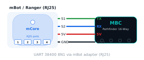
Get the MakeBlock edition (RJ25 plug) and plug it into an RJ25 port of mBot / Ranger / Orion / MegaPi; usable ports per board are listed in MakeBlock extension.
Setup
What you need
- Sensor: Pathfinder 16-Way (Line16) (MakeBlock edition, different factory firmware from the other editions), plus an mBot adapter (to plug into an RJ25 port). SPIKE, EV3 and I2C editions cannot connect to a Makeblock board directly.
- Board: mBot (mCore), mBot Ranger (Auriga), Orion, Ultimate 2.0 (MegaPi), MegaPi Pro. mBot2 (CyberPi) has no RJ25 port and is not supported.
- Software: mBlock 5 for PC (Upload mode: the program is flashed to the board).
- Extension: MBC Pro Sensors v2.0.0 (for protocol v2 firmware shipped from 2026-10).
Install the software
- Install mBlock 5 for PC from the mBlock website.
- Open mBlock 5 and add your board (for example mBot) under "Devices" at the bottom left.
- Switch the mode toggle at the bottom right to Upload.
Make the software see the sensor
Add one extension and the MBC blocks appear:
- Get the v2.0.0 extension: once it is listed, search "MBC" in the mBlock 5 "Extension Center" and add it. Before it is listed (under review), advanced users can sign in to ext.mblock.cc with their own Makeblock account → My extensions → Import data, upload mbc_pro_sensors_2.0.0_import.mext (about 1 minute), then click "Download" to get a
.mext. - Drag the
.mextfile into the mBlock window. Six new categories appear: Pathfinder, Ranger, Controller, IMU gyro, Vision and MBC common. - Start the program with the board's start block (for example "when mBot starts up") and click "Upload" to flash it to the board.
- To open an example: "File → Open from your computer" and pick the
.mblockfile.
Important
The new extension (v2) only works with new firmware, and the legacy extension (v1.0.0) only with firmware from before 2026-10; their blocks are not compatible. Not sure which firmware you have? Drag in the v2 extension and read the "MBC common → protocol version" block: 2 means new firmware. The legacy extension is in the Downloads.
Wiring
Sensor → mBot adapter → the board's RJ25 port (UART 38400). The blocks ask for a port number; the extension maps it to the right pins for your board.
| Board | Usable ports | Notes |
|---|---|---|
| mBot (mCore) | 1, 2, 3, 4 | all four ports |
| mBot Ranger (Auriga) | 6 ~ 10 | 1 ~ 4 are red motor ports, 5 is the serial port |
| Orion | 3, 4, 6 | 1, 2 are red motor ports; 7, 8 are analog only |
| Ultimate 2.0 (MegaPi) | 6, 7, 8 | needs the RJ25 shield; 5 is the serial port |
| MegaPi Pro | 7, 8, 9, 10 | needs the RJ25 shield |
The examples on this page use mBot port 1; to use another port, change the port number on the blocks. On another board, replace "when mBot starts up" with that board's start block.
Calibrate first (only once)
The Pathfinder has to "learn" the black and white of your mat before its numbers are right. Calibration is stored in the sensor and survives power-off (until you change mats).
- Plug in the sensor and turn the hub on (the sensor lights come on).
- Hold the calibration button for about 0.5 s, then release it (do not keep holding it; holding it keeps restarting calibration).
- When the green calibration LED (next to the button) lights up, sweep the sensor back and forth between the black line and the white floor within 5 seconds. All 16 sensing points must pass over the darkest black line and the brightest white area.
- Keep the sensor 3~12 mm above the surface while sweeping; higher reads poorly.
- The green LED goes off = calibration done, saved in the sensor automatically.
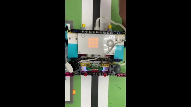
How do I know it worked? On the white floor the "line width" is 0; on a normal black line it is 3~5.
Tip
You can also calibrate with a block: "Pathfinder port [port] 5-second sweep calibration" does the same as the button.
Old firmware and old blocks
The legacy extension v1.0.0 (15 blocks) goes with firmware shipped before 2026-10. To use the old blocks with new firmware, the Pathfinder 8 / 16 can be flashed with the MBC_MBLOCK_LEGACY=1 build (no legacy build exists for the other products).
First test
- Start the program with "wait 1 second" so the sensor can boot; reading too early returns
-32768. - Check the wiring with the "MBC common → connection OK?" block, then look at the values.
- Upload example 1 on this page. If the number changes with the sensor, everything is connected.
FAQ
- "connection OK?" is false? Wrong port, the sensor is not the MakeBlock edition, or the firmware is legacy (use the v1 extension with old firmware).
- Reading
-32768? Nothing has been read since power-on: check the wiring; or this product has no such value. - The value never changes? Make sure the adapter is firmly in and the sensor light is on; "protocol version" reading 2 means communication works.
- Still stuck? Contact us on LINE with the board model, the port and the value of the "device ID" block.
Reading values
After adding the MBC Pro Sensors extension, find the blocks in the "Pathfinder" category and pick the port the sensor is plugged into.
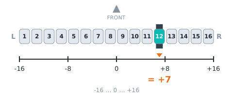
line position linePos
| Range | Meaning |
|---|---|
-16~+16 |
which channel the line is under: −16 (far left) to +16 (far right), 0 = centre; seen from behind the robot, negative = left (normally ±15; ±16 only for 200 ms after the line leaves the outermost channel) |
(Pathfinder port [1 v] line position :: sensing)
Block returns line position(-16~+16)。Host sends [01] → reply [lo][hi][01 ^ lo ^ hi], value = int16 little-endian.
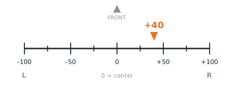
fine position linePosFine
| Range | Meaning |
|---|---|
-100~+100 |
sub-channel position: −100 to +100, 0 = centre, negative = left (same sign as line position) |
(Pathfinder port [1 v] fine line position :: sensing)
Block returns fine position(-100~+100)。Host sends [02] → reply [lo][hi][02 ^ lo ^ hi], value = int16 little-endian.
line width lineWidth
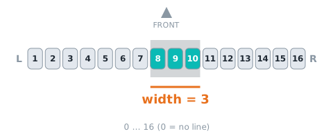
| Range | Meaning |
|---|---|
0~16 路 |
number of channels on the line, 0~16; 0 = no line |
(Pathfinder port [1 v] line width :: sensing)
Block returns line width(0~16 路)。Host sends [03] → reply [lo][hi][03 ^ lo ^ hi], value = int16 little-endian.
line segments groupCount
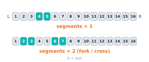
| Range | Meaning |
|---|---|
0~8 |
number of separate line segments: 0 = lost, 1 = one line, ≥2 = fork / crossing |
(Pathfinder port [1 v] line segments :: sensing)
Block returns line segments(0~8)。Host sends [04] → reply [lo][hi][04 ^ lo ^ hi], value = int16 little-endian.
line bitmap bitmap
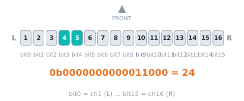
| Range | Meaning |
|---|---|
0~65535 bit |
bit0 = channel 1 (left) … bit15 = channel 16; 1 = that channel sees the line |
(Pathfinder port [1 v] line bitmap :: sensing)
Block returns line bitmap(0~65535 bit)。Host sends [05] → reply [lo][hi][05 ^ lo ^ hi], value = int16 little-endian.
last exit direction lastDir
| Range | Meaning |
|---|---|
-16~+16 |
where the line was before it was lost: −16 to +16 (negative = left); keeps the last value |
(Pathfinder port [1 v] last exit direction :: sensing)
Block returns last exit direction(-16~+16)。Host sends [06] → reply [lo][hi][06 ^ lo ^ hi], value = int16 little-endian.
threshold threshold
| Range | Meaning |
|---|---|
1~99 |
reflect threshold for 'on line', 1~99, default 40 (firmware shipped before 2026-11-03: 50); set with E4 |
(Pathfinder port [1 v] threshold :: sensing)
Block returns threshold(1~99)。Host sends [07] → reply [lo][hi][07 ^ lo ^ hi], value = int16 little-endian.
calibrations done calibCount
| Range | Meaning |
|---|---|
0~255 次 |
number of calibrations completed since power-on (button calibrations included) |
(Pathfinder port [1 v] calibration count :: sensing)
Block returns calibrations done(0~255 次)。Host sends [08] → reply [lo][hi][08 ^ lo ^ hi], value = int16 little-endian.
channel 1~16 reflect light
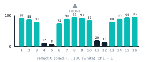
| Range | Meaning |
|---|---|
0~100 |
calibrated reflect of channel 1 |
(Pathfinder port [1 v] channel [1 v] reflect :: sensing)
Block returns channel 1~16 reflect(0~100)。Host sends [10] → reply [lo][hi][10 ^ lo ^ hi], value = int16 little-endian; channel N uses id 0x10 + (N − 1).
channel N on line? onLine
| Range | Meaning |
|---|---|
| true/false | bit N−1 of line bitmap 05 (channel 1 = bit0, leftmost): true when that channel sees the line |
Commands
black line mode blackLine
follow a black line (default); RAM only, back to the default after reset
Pathfinder port [1 v] black line mode :: sensing
Host sends [E0] → reply [00][00][E0] (ack), then it runs.
white line mode whiteLine
follow a white line (F3 b1 = 1); RAM only, back to the default after reset
Pathfinder port [1 v] white line mode :: sensing
Host sends [E1] → reply [00][00][E1] (ack), then it runs.
calibrate black calibBlack
store the current reading as black (sensor over the black line), ~50 ms; saved to EEPROM
Pathfinder port [1 v] calibrate black :: sensing
Host sends [E2] → reply [00][00][E2] (ack), then it runs; F3 bit2 = 1 while busy.
calibrate white calibWhite
store the current reading as white (sensor over the white surface), ~50 ms; saved to EEPROM
Pathfinder port [1 v] calibrate white :: sensing
Host sends [E3] → reply [00][00][E3] (ack), then it runs; F3 bit2 = 1 while busy.
set threshold setThreshold
threshold 1~99 (RAM only, back to 40 after reboot); on SPIKE an out-of-range value returns failed (state 2)
Pathfinder port [1 v] set threshold (50) :: sensing
Host sends [E4][params…] → reply [00][00][E4] (ack), then it runs.
5-second auto calibration calibAuto
sweep the sensor across black line and white surface for 5 s; min/max become the references; F3 b2 = 1 meanwhile
Pathfinder port [1 v] 5-second auto calibration :: sensing
Host sends [E7] → reply [00][00][E7] (ack), then it runs; F3 bit2 = 1 while busy.
update all values readAll
reads the whole value table into a cache (FD pack-all); reporter blocks within the next 10 ms use the cache instead of asking one by one
Pathfinder port [1 v] update all values :: sensing
Not available here:mirror left/right
Examples
This page is for people who have never written a program: read the Pathfinder 16-Way on an mBot with mBlock 5 blocks. The 5 examples start with "turn the number into a sound" and work up to a robot that drives itself. Every example has a block picture, a downloadable project file and an Arduino sketch that does the same thing.
| Software | Who it suits | How to open the example file |
|---|---|---|
| 🟧 mBlock 5 desktop (blocks, Upload mode) + MBC Pro Sensors extension v2 | Schools, first time with an mBot | Download the .mblock → open mBlock 5 → "File → Open from your computer" → switch to "Upload" at the bottom right → "Upload" |
| 🔧 Arduino IDE (text code) | People who want to see what is behind the blocks, or write their own code | Download the .ino → install the Makeblock and MBC_Sensors libraries (see Makeblock extension) → board Arduino Uno → upload |
Important
- The sensor must be the Makeblock edition with the 2026-10 protocol v2 firmware, connected through the mBot socket board to an RJ25 port; use extension v2.0.0 (old firmware goes with the old v1 extension; they cannot be mixed).
- The board is the mBot (mCore). mBot Ranger, Orion and MegaPi work too: swap "when mBot starts up" for that board's hat block and use a port that board allows (see supported boards and ports); the mBot2 (CyberPi) has no RJ25 port and is not supported.
- mBlock 5 is shown here with its English block text; your copy may show the same blocks in another language.
Before you start
Sensor → mBot socket board → RJ25 port on the board (S1 = host TX, S2 = host RX, UART 38400).
- Install the extension: get the MBC Pro Sensors v2.0.0
.mextfrom Makeblock extension and drop it into the mBlock 5 window; add mBot under "Devices" (bottom left) and switch to "Upload" (bottom right). - Wiring: Pathfinder → mBot socket board → mBot port 1 (every example on this page uses this port; to use another, change the port number on the blocks).
- Let it boot first: every example starts with "wait 1 seconds" so the sensor can boot; reading too early gives -32768 (nothing received yet).
- Calibrate once: with the sensor plugged in and the mBot on, press and release the calibration button on the sensor, then within the 5 s the green LED is on sweep the sensor back and forth across the black line and white surface (all 16 spots must see both). Green LED off = done; it is stored in the sensor. The block "Pathfinder port 1 5-second auto calibration" does the same.
- How do you know it worked? Run example 2: on plain white the LED goes off (line width 0); over the black line it lights.
Blocks used on this page
Each reporter block is one "value id" of the sensor's value table (the same ids as the Arduino I2C registers); the full block list is in Makeblock extension.
| Block | Returns | Meaning |
|---|---|---|
| Pathfinder port [1] fine line position | -100~+100 | sub-channel position: −100 to +100, 0 = centre, negative = left (same sign as line position) |
| Pathfinder port [1] line width | 0~16 路 | number of channels on the line, 0~16; 0 = no line |
| Pathfinder port [1] line position | -16~+16 | which channel the line is under: −16 (far left) to +16 (far right), 0 = centre; seen from behind the robot, negative = left (normally ±15; ±16 only for 200 ms after the line leaves the outermost channel) |
Examples on this page
- Hear where the line is
- The LED shows which side the line is on
- The line position drives one wheel
- Three-way line following
- Proportional line following + stop when the line is lost
Note
The
.mblockfiles are generated in the mBlock 5 save format and have not yet been opened in mBlock 5 for verification (pending the extension v2 release). If one will not open or shows blank blocks, check that extension v2 is loaded and the device is mBot, or rebuild it from the block picture below (under 5 minutes); you can also tell us on LINE.
Example 1: Hear where the line is
What this example does: The mBot has no screen, so this example turns the "fine line position" (−100 to +100) into a pitch: 440 Hz (A) with the line in the centre, lower to the left and higher to the right. Learn to "read the number" first; the line-following examples build on it.
What you need
- mBot (mCore board) + mBlock 5 desktop
- Pathfinder 16-Way (Makeblock edition) + mBot socket board
- A white mat with a black line (about 2 cm wide)
Wiring: Pathfinder → mBot socket board → mBot port 1. Mount it under the front of the robot about 1 cm above the ground, facing straight down.
Download
| mBlock 5 project | Equivalent Arduino sketch |
|---|---|
| ex01_hear_line.mblock | ex01_hear_line.ino |
mBlock blocks (just rebuild them like this)
when mBot starts up :: events hat
wait (1) seconds
forever
  play tone ((440) + ((Pathfinder port [1 v] fine line position :: #9300DB) * (2))) Hz for (0.1) seconds :: sound
end
🔧 Equivalent Arduino sketch (mBot)
// Pathfinder 16-Way × mBlock 5  Example 1: Hear where the line is  (equivalent Arduino sketch for mBot)
// Wiring: Pathfinder → mBot socket board → mBot port 1. Mount it under the front of the robot about 1 cm above the ground, facing straight down.
// Does exactly what the mBlock block example does, for people who want to see "what is behind the blocks" or use the Arduino IDE.
// Libraries needed:
//   1. Makeblock (Arduino IDE Library Manager, search "Makeblock", or the copy inside the mBlock 5 install folder)
//   2. MBC_Sensors v2: the four files in src/ of the extension .mext (MBC_Sensors.h/.cpp, mbc_proto.h, mbc_ids.h),
//      put them in Documents/Arduino/libraries/MBC_Sensors/ and #include <MBC_Sensors.h> (https://mbc-pro-sensors.github.io/en/makeblock.html)
// Board: Arduino Uno (the mBot mCore is an Uno). After uploading, unplug USB and run on battery.

#include <MeMCore.h>            // mBot (mCore): motors, LED, buzzer
#include <SoftwareSerial.h>
#include <MBC_Sensors.h>        // MBC sensors v2 (the same library the mBlock extension uses)

MBCPort mbc_port1(1);           // sensor on mBot port 1
MeDCMotor motorL(9);           // left wheel (M1)
MeDCMotor motorR(10);          // right wheel (M2)
MeRGBLed rgbled(7, 2);         // on-board RGB LED (2 pixels)
MeBuzzer buzzer;               // on-board buzzer

// left / right wheel power -100~100 (positive = forward): the mBot left wheel is mounted mirrored, so M1 gets the negative value; % becomes PWM 0~255
void wheels(int l, int r) {
  l = constrain(l, -100, 100); r = constrain(r, -100, 100);
  motorL.run(-l * 255 / 100);
  motorR.run(r * 255 / 100);
}

void setup() {   // everything runs inside setup(), just like the program mBlock generates
  mbc_port1.begin();
  delay(1000);   // Wait 1 s for the sensor to boot
  while (1) {   // Repeat forever
    buzzer.tone((440 + (mbcRead(mbc_port1, 0x02) * 2)), 100);   // Pitch = 440 + fine line position × 2 Hz, for 0.1 s
  }
}

void loop() {}   // nothing here: the blocks above never return
Step by step
- Wait 1 s for the sensor to boot
- Repeat forever
- Pitch = 440 + fine line position × 2 Hz, for 0.1 s
What you should see: Black line under the centre of the sensor: 440 Hz. Slide the line to the left and the pitch drops (240 Hz at the far left); to the right it rises (640 Hz at the far right). Remove the line and the pitch stays where the line was last seen.
FAQ
- No sound? → The buzzer is on the board and is not loud; listen closely, or change 0.1 s to 0.3 s.
- Pitch goes the wrong way? → Left and right are seen from behind the robot, facing forward. Mounting the sensor rotated 180° reverses it.
- "Line width" is still 0 on the black line? → Not calibrated yet: calibrate once with the button on the sensor (see "Before you start").
- Nothing happens, or the value stays at -32768? → Wrong port (every example on this page uses port 1), socket board not seated, or the sensor is not the Makeblock edition. Check with the "MBC common → connected?" block first; "protocol version" must read 2 for the new firmware (old firmware needs extension v1).
- Upload fails, or the blocks are blank? → Make sure the switch at the bottom right is in "Upload" mode, extension v2 has been dropped into mBlock, and the USB cable goes to the mBot board.
Example 2: The LED shows which side the line is on
What this example does: Use "if… then… else…" on the line position: left = red, right = blue, centre = green; line width 0 (no line) = LED off. This is the skeleton of every line follower; the next example just swaps the LED for the wheels.
What you need
- mBot (mCore board) + mBlock 5 desktop
- Pathfinder 16-Way (Makeblock edition) + mBot socket board
- A white mat with a black line (about 2 cm wide)
Wiring: Pathfinder → mBot socket board → mBot port 1. Mount it under the front of the robot about 1 cm above the ground, facing straight down.
Download
| mBlock 5 project | Equivalent Arduino sketch |
|---|---|
| ex02_led_side.mblock | ex02_led_side.ino |
mBlock blocks (just rebuild them like this)
when mBot starts up :: events hat
wait (1) seconds
forever
  if <(Pathfinder port [1 v] line width :: #9300DB) = (0)> then
    LED [all v] colour red (0) green (0) blue (0) :: looks
  else
    if <(Pathfinder port [1 v] line position :: #9300DB) < (-4)> then
      LED [all v] colour red (255) green (0) blue (0) :: looks
    else
      if <(Pathfinder port [1 v] line position :: #9300DB) > (4)> then
        LED [all v] colour red (0) green (0) blue (255) :: looks
      else
        LED [all v] colour red (0) green (255) blue (0) :: looks
      end
    end
  end
end
🔧 Equivalent Arduino sketch (mBot)
// Pathfinder 16-Way × mBlock 5  Example 2: The LED shows which side the line is on  (equivalent Arduino sketch for mBot)
// Wiring: Pathfinder → mBot socket board → mBot port 1. Mount it under the front of the robot about 1 cm above the ground, facing straight down.
// Does exactly what the mBlock block example does, for people who want to see "what is behind the blocks" or use the Arduino IDE.
// Libraries needed:
//   1. Makeblock (Arduino IDE Library Manager, search "Makeblock", or the copy inside the mBlock 5 install folder)
//   2. MBC_Sensors v2: the four files in src/ of the extension .mext (MBC_Sensors.h/.cpp, mbc_proto.h, mbc_ids.h),
//      put them in Documents/Arduino/libraries/MBC_Sensors/ and #include <MBC_Sensors.h> (https://mbc-pro-sensors.github.io/en/makeblock.html)
// Board: Arduino Uno (the mBot mCore is an Uno). After uploading, unplug USB and run on battery.

#include <MeMCore.h>            // mBot (mCore): motors, LED, buzzer
#include <SoftwareSerial.h>
#include <MBC_Sensors.h>        // MBC sensors v2 (the same library the mBlock extension uses)

MBCPort mbc_port1(1);           // sensor on mBot port 1
MeDCMotor motorL(9);           // left wheel (M1)
MeDCMotor motorR(10);          // right wheel (M2)
MeRGBLed rgbled(7, 2);         // on-board RGB LED (2 pixels)
MeBuzzer buzzer;               // on-board buzzer

// left / right wheel power -100~100 (positive = forward): the mBot left wheel is mounted mirrored, so M1 gets the negative value; % becomes PWM 0~255
void wheels(int l, int r) {
  l = constrain(l, -100, 100); r = constrain(r, -100, 100);
  motorL.run(-l * 255 / 100);
  motorR.run(r * 255 / 100);
}

void setup() {   // everything runs inside setup(), just like the program mBlock generates
  mbc_port1.begin();
  delay(1000);   // Wait 1 s for the sensor to boot
  while (1) {   // Repeat forever
    if ((mbcRead(mbc_port1, 0x03) == 0)) {   // If the line width = 0 (no line)
      rgbled.setColor(0, 0, 0, 0); rgbled.show();   // No line: LED off
    } else {
      if ((mbcRead(mbc_port1, 0x01) < -4)) {   // Otherwise, if the line position is less than -4 (left)
        rgbled.setColor(0, 255, 0, 0); rgbled.show();   // Line to the left: red
      } else {
        if ((mbcRead(mbc_port1, 0x01) > 4)) {   // Otherwise, if the line position is greater than 4 (right)
          rgbled.setColor(0, 0, 0, 255); rgbled.show();   // Line to the right: blue
        } else {
          rgbled.setColor(0, 0, 255, 0); rgbled.show();   // Line in the centre: green
        }
      }
    }
  }
}

void loop() {}   // nothing here: the blocks above never return
Step by step
- Wait 1 s for the sensor to boot
- Repeat forever
- If the line width = 0 (no line)
- No line: LED off
- otherwise:
- Otherwise, if the line position is less than -4 (left)
- Line to the left: red
- otherwise:
- Otherwise, if the line position is greater than 4 (right)
- Line to the right: blue
- otherwise:
- Line in the centre: green
- Otherwise, if the line position is greater than 4 (right)
- Otherwise, if the line position is less than -4 (left)
- If the line width = 0 (no line)
What you should see: Line in the centre: green. Move it more than 4 channels to the left: red; to the right: blue. On plain white the LED goes off.
FAQ
- How do I change the colours? → Edit the three red/green/blue numbers (0~255); 255, 255, 0 is yellow, for example.
- "Line width" is still 0 on the black line? → Not calibrated yet: calibrate once with the button on the sensor (see "Before you start").
- Nothing happens, or the value stays at -32768? → Wrong port (every example on this page uses port 1), socket board not seated, or the sensor is not the Makeblock edition. Check with the "MBC common → connected?" block first; "protocol version" must read 2 for the new firmware (old firmware needs extension v1).
- Upload fails, or the blocks are blank? → Make sure the switch at the bottom right is in "Upload" mode, extension v2 has been dropped into mBlock, and the USB cable goes to the mBot board.
Example 3: The line position drives one wheel
What this example does: Divide the "fine line position" (−100 to +100) by 2 and use it directly as the left wheel power: line on the right → forward, on the left → backward, centre → still; the further off, the faster. Prop the robot up (wheels off the ground) to watch one wheel follow the line, then put it down in the next example.
What you need
- mBot (mCore board) + mBlock 5 desktop
- mBot two-wheel robot (left wheel on M1, right wheel on M2, as shipped)
- Pathfinder 16-Way (Makeblock edition) + mBot socket board
- A white mat with a black line (about 2 cm wide)
Wiring: Pathfinder → mBot socket board → mBot port 1. Mount it under the front of the robot about 1 cm above the ground, facing straight down.
Download
| mBlock 5 project | Equivalent Arduino sketch |
|---|---|
| ex03_one_wheel.mblock | ex03_one_wheel.ino |
mBlock blocks (just rebuild them like this)
when mBot starts up :: events hat
wait (1) seconds
forever
  left wheel power ((Pathfinder port [1 v] fine line position :: #9300DB) / (2)) %, right wheel power (0) % :: motion
end
🔧 Equivalent Arduino sketch (mBot)
// Pathfinder 16-Way × mBlock 5  Example 3: The line position drives one wheel  (equivalent Arduino sketch for mBot)
// Wiring: Pathfinder → mBot socket board → mBot port 1. Mount it under the front of the robot about 1 cm above the ground, facing straight down.
// Does exactly what the mBlock block example does, for people who want to see "what is behind the blocks" or use the Arduino IDE.
// Libraries needed:
//   1. Makeblock (Arduino IDE Library Manager, search "Makeblock", or the copy inside the mBlock 5 install folder)
//   2. MBC_Sensors v2: the four files in src/ of the extension .mext (MBC_Sensors.h/.cpp, mbc_proto.h, mbc_ids.h),
//      put them in Documents/Arduino/libraries/MBC_Sensors/ and #include <MBC_Sensors.h> (https://mbc-pro-sensors.github.io/en/makeblock.html)
// Board: Arduino Uno (the mBot mCore is an Uno). After uploading, unplug USB and run on battery.

#include <MeMCore.h>            // mBot (mCore): motors, LED, buzzer
#include <SoftwareSerial.h>
#include <MBC_Sensors.h>        // MBC sensors v2 (the same library the mBlock extension uses)

MBCPort mbc_port1(1);           // sensor on mBot port 1
MeDCMotor motorL(9);           // left wheel (M1)
MeDCMotor motorR(10);          // right wheel (M2)
MeRGBLed rgbled(7, 2);         // on-board RGB LED (2 pixels)
MeBuzzer buzzer;               // on-board buzzer

// left / right wheel power -100~100 (positive = forward): the mBot left wheel is mounted mirrored, so M1 gets the negative value; % becomes PWM 0~255
void wheels(int l, int r) {
  l = constrain(l, -100, 100); r = constrain(r, -100, 100);
  motorL.run(-l * 255 / 100);
  motorR.run(r * 255 / 100);
}

void setup() {   // everything runs inside setup(), just like the program mBlock generates
  mbc_port1.begin();
  delay(1000);   // Wait 1 s for the sensor to boot
  while (1) {   // Repeat forever
    wheels((mbcRead(mbc_port1, 0x02) / 2), 0);   // Left wheel power = fine line position ÷ 2 (−50 to +50), right wheel 0
  }
}

void loop() {}   // nothing here: the blocks above never return
Step by step
- Wait 1 s for the sensor to boot
- Repeat forever
- Left wheel power = fine line position ÷ 2 (−50 to +50), right wheel 0
What you should see: Line in the centre: the left wheel is still. Move the line right: the left wheel turns forward, faster the further off; move it left: the wheel reverses.
FAQ
- The robot turns the wrong way and gets worse? → Swap the "+" and "−" (or swap the left and right wheel powers). The mBot ships with the left wheel on M1 and the right on M2; check your own wiring.
- The wheel creeps with the line in the centre? → The fine position is not always exactly 0. Add "if line width = 0 or the absolute value is below 6 then power 0" to hold still.
- "Line width" is still 0 on the black line? → Not calibrated yet: calibrate once with the button on the sensor (see "Before you start").
- Nothing happens, or the value stays at -32768? → Wrong port (every example on this page uses port 1), socket board not seated, or the sensor is not the Makeblock edition. Check with the "MBC common → connected?" block first; "protocol version" must read 2 for the new firmware (old firmware needs extension v1).
- Upload fails, or the blocks are blank? → Make sure the switch at the bottom right is in "Upload" mode, extension v2 has been dropped into mBlock, and the USB cable goes to the mBot board.
Example 4: Three-way line following
What this example does: Swap the LED of example 2 for the wheels: line on the left → left wheel slow, right wheel fast (steer left); on the right the opposite; in the centre both wheels equal. The robot wiggles along the black line: the simplest line follower and the easiest to understand.
What you need
- mBot (mCore board) + mBlock 5 desktop
- mBot two-wheel robot (left wheel on M1, right wheel on M2, as shipped)
- Pathfinder 16-Way (Makeblock edition) + mBot socket board
- A white mat with a black line (about 2 cm wide)
Wiring: Pathfinder → mBot socket board → mBot port 1. Mount it under the front of the robot about 1 cm above the ground, facing straight down.
Download
| mBlock 5 project | Equivalent Arduino sketch |
|---|---|
| ex04_three_way.mblock | ex04_three_way.ino |
mBlock blocks (just rebuild them like this)
when mBot starts up :: events hat
wait (1) seconds
forever
  if <(Pathfinder port [1 v] line position :: #9300DB) < (-4)> then
    left wheel power (10) %, right wheel power (40) % :: motion
  else
    if <(Pathfinder port [1 v] line position :: #9300DB) > (4)> then
      left wheel power (40) %, right wheel power (10) % :: motion
    else
      left wheel power (30) %, right wheel power (30) % :: motion
    end
  end
end
🔧 Equivalent Arduino sketch (mBot)
// Pathfinder 16-Way × mBlock 5  Example 4: Three-way line following  (equivalent Arduino sketch for mBot)
// Wiring: Pathfinder → mBot socket board → mBot port 1. Mount it under the front of the robot about 1 cm above the ground, facing straight down.
// Does exactly what the mBlock block example does, for people who want to see "what is behind the blocks" or use the Arduino IDE.
// Libraries needed:
//   1. Makeblock (Arduino IDE Library Manager, search "Makeblock", or the copy inside the mBlock 5 install folder)
//   2. MBC_Sensors v2: the four files in src/ of the extension .mext (MBC_Sensors.h/.cpp, mbc_proto.h, mbc_ids.h),
//      put them in Documents/Arduino/libraries/MBC_Sensors/ and #include <MBC_Sensors.h> (https://mbc-pro-sensors.github.io/en/makeblock.html)
// Board: Arduino Uno (the mBot mCore is an Uno). After uploading, unplug USB and run on battery.

#include <MeMCore.h>            // mBot (mCore): motors, LED, buzzer
#include <SoftwareSerial.h>
#include <MBC_Sensors.h>        // MBC sensors v2 (the same library the mBlock extension uses)

MBCPort mbc_port1(1);           // sensor on mBot port 1
MeDCMotor motorL(9);           // left wheel (M1)
MeDCMotor motorR(10);          // right wheel (M2)
MeRGBLed rgbled(7, 2);         // on-board RGB LED (2 pixels)
MeBuzzer buzzer;               // on-board buzzer

// left / right wheel power -100~100 (positive = forward): the mBot left wheel is mounted mirrored, so M1 gets the negative value; % becomes PWM 0~255
void wheels(int l, int r) {
  l = constrain(l, -100, 100); r = constrain(r, -100, 100);
  motorL.run(-l * 255 / 100);
  motorR.run(r * 255 / 100);
}

void setup() {   // everything runs inside setup(), just like the program mBlock generates
  mbc_port1.begin();
  delay(1000);   // Wait 1 s for the sensor to boot
  while (1) {   // Repeat forever
    if ((mbcRead(mbc_port1, 0x01) < -4)) {   // If the line position is less than -4 (left)
      wheels(10, 40);   // Line to the left: left wheel slow, right wheel fast, steer left
    } else {
      if ((mbcRead(mbc_port1, 0x01) > 4)) {   // Otherwise, if the line position is greater than 4 (right)
        wheels(40, 10);   // Line to the right: left wheel fast, right wheel slow, steer right
      } else {
        wheels(30, 30);   // Line in the centre: both wheels equal, straight ahead
      }
    }
  }
}

void loop() {}   // nothing here: the blocks above never return
Step by step
- Wait 1 s for the sensor to boot
- Repeat forever
- If the line position is less than -4 (left)
- Line to the left: left wheel slow, right wheel fast, steer left
- otherwise:
- Otherwise, if the line position is greater than 4 (right)
- Line to the right: left wheel fast, right wheel slow, steer right
- otherwise:
- Line in the centre: both wheels equal, straight ahead
- Otherwise, if the line position is greater than 4 (right)
- If the line position is less than -4 (left)
What you should see: The robot wiggles its way along the black line. If it flies off on sharp bends, lower the 40 and change the 10 to 0.
FAQ
- The robot turns the wrong way and gets worse? → Swap the "+" and "−" (or swap the left and right wheel powers). The mBot ships with the left wheel on M1 and the right on M2; check your own wiring.
- "Line width" is still 0 on the black line? → Not calibrated yet: calibrate once with the button on the sensor (see "Before you start").
- Nothing happens, or the value stays at -32768? → Wrong port (every example on this page uses port 1), socket board not seated, or the sensor is not the Makeblock edition. Check with the "MBC common → connected?" block first; "protocol version" must read 2 for the new firmware (old firmware needs extension v1).
- Upload fails, or the blocks are blank? → Make sure the switch at the bottom right is in "Upload" mode, extension v2 has been dropped into mBlock, and the USB cable goes to the mBot board.
Example 5: Proportional line following + stop when the line is lost
What this example does: Three-way following keeps wiggling. This example uses "fine line position × 0.3" as the steering force: a little off = a little turn, far off = a big turn, so the drive is smoother. Line width detects a lost line: no line → stop with a red LED, following normally → green. This is the starting point for competition line followers.
What you need
- mBot (mCore board) + mBlock 5 desktop
- mBot two-wheel robot (left wheel on M1, right wheel on M2, as shipped)
- Pathfinder 16-Way (Makeblock edition) + mBot socket board
- A white mat with a black line (about 2 cm wide)
Wiring: Pathfinder → mBot socket board → mBot port 1. Mount it under the front of the robot about 1 cm above the ground, facing straight down.
Download
| mBlock 5 project | Equivalent Arduino sketch |
|---|---|
| ex05_p_follow.mblock | ex05_p_follow.ino |
mBlock blocks (just rebuild them like this)
when mBot starts up :: events hat
wait (1) seconds
forever
  if <(Pathfinder port [1 v] line width :: #9300DB) = (0)> then
    stop moving :: motion
    LED [all v] colour red (255) green (0) blue (0) :: looks
  else
    set [turn v] to ((Pathfinder port [1 v] fine line position :: #9300DB) * (0.3))
    left wheel power ((30) + (turn)) %, right wheel power ((30) - (turn)) % :: motion
    LED [all v] colour red (0) green (255) blue (0) :: looks
  end
end
🔧 Equivalent Arduino sketch (mBot)
// Pathfinder 16-Way × mBlock 5  Example 5: Proportional line following + stop when the line is lost  (equivalent Arduino sketch for mBot)
// Wiring: Pathfinder → mBot socket board → mBot port 1. Mount it under the front of the robot about 1 cm above the ground, facing straight down.
// Does exactly what the mBlock block example does, for people who want to see "what is behind the blocks" or use the Arduino IDE.
// Libraries needed:
//   1. Makeblock (Arduino IDE Library Manager, search "Makeblock", or the copy inside the mBlock 5 install folder)
//   2. MBC_Sensors v2: the four files in src/ of the extension .mext (MBC_Sensors.h/.cpp, mbc_proto.h, mbc_ids.h),
//      put them in Documents/Arduino/libraries/MBC_Sensors/ and #include <MBC_Sensors.h> (https://mbc-pro-sensors.github.io/en/makeblock.html)
// Board: Arduino Uno (the mBot mCore is an Uno). After uploading, unplug USB and run on battery.

#include <MeMCore.h>            // mBot (mCore): motors, LED, buzzer
#include <SoftwareSerial.h>
#include <MBC_Sensors.h>        // MBC sensors v2 (the same library the mBlock extension uses)

MBCPort mbc_port1(1);           // sensor on mBot port 1
MeDCMotor motorL(9);           // left wheel (M1)
MeDCMotor motorR(10);          // right wheel (M2)
MeRGBLed rgbled(7, 2);         // on-board RGB LED (2 pixels)
MeBuzzer buzzer;               // on-board buzzer
float turn = 0;               // variable:turn

// left / right wheel power -100~100 (positive = forward): the mBot left wheel is mounted mirrored, so M1 gets the negative value; % becomes PWM 0~255
void wheels(int l, int r) {
  l = constrain(l, -100, 100); r = constrain(r, -100, 100);
  motorL.run(-l * 255 / 100);
  motorR.run(r * 255 / 100);
}

void setup() {   // everything runs inside setup(), just like the program mBlock generates
  mbc_port1.begin();
  delay(1000);   // Wait 1 s for the sensor to boot
  while (1) {   // Repeat forever
    if ((mbcRead(mbc_port1, 0x03) == 0)) {   // If the line width = 0 (no line)
      wheels(0, 0);   // No line: stop
      rgbled.setColor(0, 255, 0, 0); rgbled.show();   // Red LED
    } else {
      turn = (mbcRead(mbc_port1, 0x02) * 0.3);   // turn = fine line position × 0.3 (−30 to +30)
      wheels((30 + turn), (30 - turn));   // Left = 30 + turn, right = 30 − turn: line on the left (negative) → left wheel slow, right wheel fast
      rgbled.setColor(0, 0, 255, 0); rgbled.show();   // Green LED
    }
  }
}

void loop() {}   // nothing here: the blocks above never return
Step by step
- Wait 1 s for the sensor to boot
- Repeat forever
- If the line width = 0 (no line)
- No line: stop
- Red LED
- otherwise:
- turn = fine line position × 0.3 (−30 to +30)
- Left = 30 + turn, right = 30 − turn: line on the left (negative) → left wheel slow, right wheel fast
- Green LED
- If the line width = 0 (no line)
What you should see: The robot follows the black line smoothly with a green LED; lift it off the line and it stops at once with a red LED. If it still wiggles on straights, lower 0.3 (e.g. 0.2); if it cannot make the bends, raise it.
FAQ
- The robot turns the wrong way and gets worse? → Swap the "+" and "−" (or swap the left and right wheel powers). The mBot ships with the left wheel on M1 and the right on M2; check your own wiring.
- Does it stop at crossings too? → No, at a crossing the line width gets larger, not 0. To stop at crossings, try "line width > 5" instead of "= 0".
- "Line width" is still 0 on the black line? → Not calibrated yet: calibrate once with the button on the sensor (see "Before you start").
- Nothing happens, or the value stays at -32768? → Wrong port (every example on this page uses port 1), socket board not seated, or the sensor is not the Makeblock edition. Check with the "MBC common → connected?" block first; "protocol version" must read 2 for the new firmware (old firmware needs extension v1).
- Upload fails, or the blocks are blank? → Make sure the switch at the bottom right is in "Upload" mode, extension v2 has been dropped into mBlock, and the USB cable goes to the mBot board.
Next steps
- All Pathfinder blocks and the usable ports per board: Makeblock extension; this product's block table: Pathfinder 16-Way × mBlock 5
- The same ideas on LEGO: EV3 beginner examples
- Arduino straight to the sensor (I2C edition, no mBot): Arduino examples
More questions
- Blocks keep returning 0? Check the port in the block matches the real port and that the program was uploaded to the board.
- Does the old extension still work? Sensors shipped before 2026-10 use the legacy v1.0.0 extension; old and new blocks are not compatible.
Still stuck? Contact us with your software and a screenshot of the program.
Downloads
- MBC_Pro_Sensors_mBlock5_v2.2.0_import.mext
- MBC_Pro_Sensors_mBlock5_v2.1.0_import.mext
- MBC_Pro_Sensors_mBlock5_v2.0.0_import.mext
- MBC_Pro_Sensors_mBlock5_v1.0.0.mext (legacy, units shipped before 2026-10)
- Download centre (libraries, firmware, catalogue for every product)
Sources
- Host and software list:
_build/guides.json - Values and commands:
_build/protocol/line16.json(single source of truth) - Setup:
_build/guides/software/mblock-mblock5.en.md、_build/guides/product/line16/mblock-mblock5.en.md - Examples:
sensors/line16/mblock-examples.md