
Controller 2.4G (PS2) × mBlock × mBlock 5
Interactive tutorialmBlock
First time? Try the interactive tutorial in your browser first, then follow the steps below with your hub.
This page covers mBlock 5 (MBC Pro Sensors extension) only: how to set it up for the Controller 2.4G (PS2) on Makeblock (mBot) + mBlock 5, how to read every value, the commands it supports and examples. Use the switcher above to change product, host or software.
Which edition and how to connect
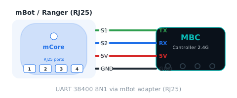
Get the MakeBlock edition (RJ25 plug) and plug it into an RJ25 port of mBot / Ranger / Orion / MegaPi; usable ports per board are listed in MakeBlock extension.
Setup
What you need
- Sensor: Controller 2.4G (PS2) (MakeBlock edition, different factory firmware from the other editions), plus an mBot adapter (to plug into an RJ25 port). SPIKE, EV3 and I2C editions cannot connect to a Makeblock board directly.
- Board: mBot (mCore), mBot Ranger (Auriga), Orion, Ultimate 2.0 (MegaPi), MegaPi Pro. mBot2 (CyberPi) has no RJ25 port and is not supported.
- Software: mBlock 5 for PC (Upload mode: the program is flashed to the board).
- Extension: MBC Pro Sensors v2.0.0 (for protocol v2 firmware shipped from 2026-10).
Install the software
- Install mBlock 5 for PC from the mBlock website.
- Open mBlock 5 and add your board (for example mBot) under "Devices" at the bottom left.
- Switch the mode toggle at the bottom right to Upload.
Make the software see the sensor
Add one extension and the MBC blocks appear:
- Get the v2.0.0 extension: once it is listed, search "MBC" in the mBlock 5 "Extension Center" and add it. Before it is listed (under review), advanced users can sign in to ext.mblock.cc with their own Makeblock account → My extensions → Import data, upload mbc_pro_sensors_2.0.0_import.mext (about 1 minute), then click "Download" to get a
.mext. - Drag the
.mextfile into the mBlock window. Six new categories appear: Pathfinder, Ranger, Controller, IMU gyro, Vision and MBC common. - Start the program with the board's start block (for example "when mBot starts up") and click "Upload" to flash it to the board.
- To open an example: "File → Open from your computer" and pick the
.mblockfile.
Important
The new extension (v2) only works with new firmware, and the legacy extension (v1.0.0) only with firmware from before 2026-10; their blocks are not compatible. Not sure which firmware you have? Drag in the v2 extension and read the "MBC common → protocol version" block: 2 means new firmware. The legacy extension is in the Downloads.
Wiring
Sensor → mBot adapter → the board's RJ25 port (UART 38400). The blocks ask for a port number; the extension maps it to the right pins for your board.
| Board | Usable ports | Notes |
|---|---|---|
| mBot (mCore) | 1, 2, 3, 4 | all four ports |
| mBot Ranger (Auriga) | 6 ~ 10 | 1 ~ 4 are red motor ports, 5 is the serial port |
| Orion | 3, 4, 6 | 1, 2 are red motor ports; 7, 8 are analog only |
| Ultimate 2.0 (MegaPi) | 6, 7, 8 | needs the RJ25 shield; 5 is the serial port |
| MegaPi Pro | 7, 8, 9, 10 | needs the RJ25 shield |
The examples on this page use mBot port 1; to use another port, change the port number on the blocks. On another board, replace "when mBot starts up" with that board's start block.
Connect the gamepad to the receiver
The PS2 2.4G gamepad and its receiver are paired at the factory; no pairing button needed.
- Connect the receiver and turn the controller on.
- Switch the gamepad on; it connects by itself.
- Watch the green LED on the receiver: on = no gamepad yet; off = gamepad connected.
- The ANALOG (or MODE) light on the gamepad must be on for the sticks to give values. The receiver switches to this mode on connect; if the light is off, press the ANALOG button in the middle of the gamepad.
Caution
2.4 GHz is a shared band (Wi-Fi, microwave ovens). With 12 or more sets in use at one venue they may interfere; in that case use the Bluetooth version (PS4 / PS5).
First test
- Start the program with "wait 1 second" so the sensor can boot; reading too early returns
-32768. - Check the wiring with the "MBC common → connection OK?" block, then look at the values.
- Upload example 1 on this page. If the number changes with the sensor, everything is connected.
FAQ
- "connection OK?" is false? Wrong port, the sensor is not the MakeBlock edition, or the firmware is legacy (use the v1 extension with old firmware).
- Reading
-32768? Nothing has been read since power-on: check the wiring; or this product has no such value. - The value never changes? Make sure the adapter is firmly in and the sensor light is on; "protocol version" reading 2 means communication works.
- Still stuck? Contact us on LINE with the board model, the port and the value of the "device ID" block.
Reading values
After adding the MBC Pro Sensors extension, find the blocks in the "Controller" category and pick the port the sensor is plugged into.
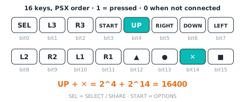
16 buttons buttons16
| Range | Meaning |
|---|---|
0~65535 bit |
all 16 buttons in one word (PSX order, 1 = pressed): bit0 SELECT, 1 L3, 2 R3, 3 START, 4 Up, 5 Right, 6 Down, 7 Left, 8 L2, 9 R2, 10 L1, 11 R1, 12 Triangle, 13 Circle, 14 Cross, 15 Square; 0 when not connected |
(Controller port [1 v] 16 buttons :: sensing)
Block returns 16 buttons(0~65535 bit)。Host sends [01] → reply [lo][hi][01 ^ lo ^ hi], value = int16 little-endian.
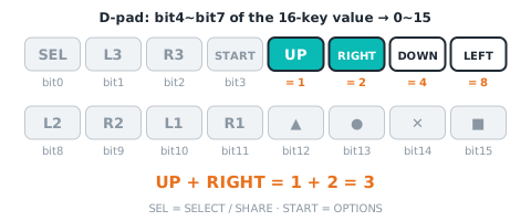
d-pad dpad
| Range | Meaning |
|---|---|
0~15 bit |
Up 1, Right 2, Down 4, Left 8 (added when pressed together), 0~15; 0 when not connected |
(Controller port [1 v] d-pad :: sensing)
Block returns d-pad(0~15 bit)。Host sends [02] → reply [lo][hi][02 ^ lo ^ hi], value = int16 little-endian.
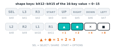
shape buttons shape
| Range | Meaning |
|---|---|
0~15 bit |
Triangle 1, Circle 2, Cross 4, Square 8 (added when pressed together), 0~15; 0 when not connected; high nibble of 0x22 'R' |
(Controller port [1 v] shape buttons :: sensing)
Block returns shape buttons(0~15 bit)。Host sends [03] → reply [lo][hi][03 ^ lo ^ hi], value = int16 little-endian.
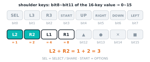
shoulder buttons shoulder
| Range | Meaning |
|---|---|
0~15 bit |
L2 1, R2 2, L1 4, R1 8 (added when pressed together), 0~15; 0 when not connected |
(Controller port [1 v] shoulder buttons :: sensing)
Block returns shoulder buttons(0~15 bit)。Host sends [04] → reply [lo][hi][04 ^ lo ^ hi], value = int16 little-endian.
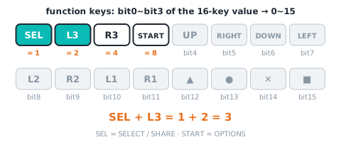
function buttons func
| Range | Meaning |
|---|---|
0~15 bit |
SELECT 1, L3 2, R3 4, START 8 (added when pressed together), 0~15; 0 when not connected; high nibble of 0x22 'G' |
(Controller port [1 v] function buttons :: sensing)
Block returns function buttons(0~15 bit)。Host sends [05] → reply [lo][hi][05 ^ lo ^ hi], value = int16 little-endian.
connected connected
| Range | Meaning |
|---|---|
0~1 |
1 = gamepad connected (psx.read() succeeds), 0 = not; while disconnected all buttons read 0 and sticks are centred |
(Controller port [1 v] gamepad connected? :: sensing)
Block returns connected(0~1)。Host sends [06] → reply [lo][hi][06 ^ lo ^ hi], value = int16 little-endian.
battery battery
| Range | Meaning |
|---|---|
0 % |
0~100; PS2 pads report no battery → always 0 (PS4 only) |
(Controller port [1 v] battery :: sensing)
Block returns battery(0 %)。Host sends [07] → reply [lo][hi][07 ^ lo ^ hi], value = int16 little-endian.
L2 analog l2Analog
| Range | Meaning |
|---|---|
0~255 |
L2 pressure 0~255 (only DualShock 2 in analog mode reports pressure; otherwise pressed = 255, released = 0); 0 when not connected |
(Controller port [1 v] L2 analog :: sensing)
Block returns L2 analog(0~255)。Host sends [08] → reply [lo][hi][08 ^ lo ^ hi], value = int16 little-endian.
R2 analog r2Analog
| Range | Meaning |
|---|---|
0~255 |
R2 pressure 0~255 (same rule as 08); 0 when not connected |
(Controller port [1 v] R2 analog :: sensing)
Block returns R2 analog(0~255)。Host sends [09] → reply [lo][hi][09 ^ lo ^ hi], value = int16 little-endian.
system keys sysKeys
| Range | Meaning |
|---|---|
0 bit |
b0 PS button, b1 capture button; PS2 pads have none → always 0 (PS4 only) |
(Controller port [1 v] system keys :: sensing)
Block returns system keys(0 bit)。Host sends [0A] → reply [lo][hi][0A ^ lo ^ hi], value = int16 little-endian.
gamepad type padType
| Range | Meaning |
|---|---|
0~2 |
0 none, 1 PS2 digital mode, 2 PS2 analog mode (3 PS4 / 4 PS5 only appear on the PS4 receiver) |
(Controller port [1 v] gamepad type :: sensing)
Block returns gamepad type(0~2)。Host sends [0B] → reply [lo][hi][0B ^ lo ^ hi], value = int16 little-endian.
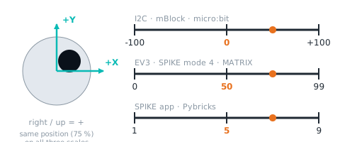
stick LX / LY / RX / RY stick
| Range | Meaning |
|---|---|
-100~+100 |
10 LX, 11 LY, 12 RX, 13 RY: −100 to +100, 0 = centre, right / up positive (raw 0 |
(Controller port [1 v] stick [LX/LY/RX/RY] :: sensing)
Block returns stick LX / LY / RX / RY(-100~+100)。Host sends [10] → reply [lo][hi][10 ^ lo ^ hi], value = int16 little-endian; channel N uses id 0x10 + (N − 1).
[button] pressed? pressed
| Range | Meaning |
|---|---|
| true/false | one button split out of 16 buttons 01 (PSX order); menu: ✕ ● ▲ ■ up down left right L1 R1 L2 R2 L3 R3 SELECT START |
Commands
rumble vibrate
[strength 0~255], 0 = stop; the PS2 receiver ACKs and ignores it (pad rumble disabled since 250614), effective on PS4 only
Controller port [1 v] rumble (128) :: sensing
Host sends [E5][params…] → reply [00][00][E5] (ack), then it runs.
light bar colour setLed
[R][G][B] 0~255 each; PS2 pads have no light bar, the receiver ACKs and ignores it, effective on PS4 only
Controller port [1 v] light bar colour (128) (128) (128) :: sensing
Host sends [E6][params…] → reply [00][00][E6] (ack), then it runs.
update all values readAll
reads the whole value table into a cache (FD pack-all); reporter blocks within the next 10 ms use the cache instead of asking one by one
Controller port [1 v] update all values :: sensing
Examples
This page is for people who have never written a program: read the Controller PS2 on an mBot with mBlock 5 blocks. The 5 examples start with "turn the number into a sound" and work up to a robot that drives itself. Every example has a block picture, a downloadable project file and an Arduino sketch that does the same thing.
| Software | Who it suits | How to open the example file |
|---|---|---|
| 🟧 mBlock 5 desktop (blocks, Upload mode) + MBC Pro Sensors extension v2 | Schools, first time with an mBot | Download the .mblock → open mBlock 5 → "File → Open from your computer" → switch to "Upload" at the bottom right → "Upload" |
| 🔧 Arduino IDE (text code) | People who want to see what is behind the blocks, or write their own code | Download the .ino → install the Makeblock and MBC_Sensors libraries (see Makeblock extension) → board Arduino Uno → upload |
Important
- The sensor must be the Makeblock edition with the 2026-10 protocol v2 firmware, connected through the mBot socket board to an RJ25 port; use extension v2.0.0 (old firmware goes with the old v1 extension; they cannot be mixed).
- The board is the mBot (mCore). mBot Ranger, Orion and MegaPi work too: swap "when mBot starts up" for that board's hat block and use a port that board allows (see supported boards and ports); the mBot2 (CyberPi) has no RJ25 port and is not supported.
- mBlock 5 is shown here with its English block text; your copy may show the same blocks in another language.
Before you start
Sensor → mBot socket board → RJ25 port on the board (S1 = host TX, S2 = host RX, UART 38400).
- Install the extension: get the MBC Pro Sensors v2.0.0
.mextfrom Makeblock extension and drop it into the mBlock 5 window; add mBot under "Devices" (bottom left) and switch to "Upload" (bottom right). - Wiring: Controller → mBot socket board → mBot port 4 (every example on this page uses this port; to use another, change the port number on the blocks).
- Let it boot first: every example starts with "wait 1 seconds" so the sensor can boot; reading too early gives -32768 (nothing received yet).
- Connect the gamepad: the PS2 2.4G gamepad and receiver are paired at the factory. Turn the gamepad on; the receiver's green LED goes off when connected (on = not yet). The ANALOG light on the gamepad must be on for the sticks to work.
- How do you know it is connected? Run example 5: green LED when connected.
Blocks used on this page
Each reporter block is one "value id" of the sensor's value table (the same ids as the Arduino I2C registers); the full block list is in Makeblock extension.
| Block | Returns | Meaning |
|---|---|---|
| Controller port [4] stick [left stick x / left stick y / right stick x / right stick y] | -100~+100 | 10 LX, 11 LY, 12 RX, 13 RY: −100 to +100, 0 = centre, right / up positive (raw 0 |
| Controller port [4] [Ⅹ / ● / ▲ / ■ / up / down / left / right / L1 / R1 / L2 / R2 / L3 / R3 / SELECT / START] pressed? | true / false | one button split out of 16 buttons 01 |
| Controller port [4] gamepad connected? | true / false | 1 = gamepad connected (psx.read() succeeds), 0 = not; while disconnected all buttons read 0 and sticks are centred |
Examples on this page
- The stick changes the pitch
- Buttons light the LED
- The left stick drives one wheel
- D-pad driving
- Tank drive + stop when disconnected
Note
The
.mblockfiles are generated in the mBlock 5 save format and have not yet been opened in mBlock 5 for verification (pending the extension v2 release). If one will not open or shows blank blocks, check that extension v2 is loaded and the device is mBot, or rebuild it from the block picture below (under 5 minutes); you can also tell us on LINE.
Example 1: The stick changes the pitch
What this example does: The mBot has no screen, so this example turns "left stick y" (−100 to +100, 0 when released) into a pitch: push up for a higher note, pull down for a lower one. Learn to "read the number" first.
What you need
- mBot (mCore board) + mBlock 5 desktop
- Controller PS2 2.4G receiver (Makeblock edition) + gamepad + mBot socket board
Wiring: 2.4G receiver → mBot socket board → mBot port 4. Turn the gamepad on; the receiver LED goes off when it is connected.
Download
| mBlock 5 project | Equivalent Arduino sketch |
|---|---|
| ex01_stick_tone.mblock | ex01_stick_tone.ino |
mBlock blocks (just rebuild them like this)
when mBot starts up :: events hat
wait (1) seconds
forever
  play tone ((440) + ((Controller port [4 v] stick [left stick y v] :: #2B6CD8) * (3))) Hz for (0.1) seconds :: sound
end
🔧 Equivalent Arduino sketch (mBot)
// Controller PS2 × mBlock 5  Example 1: The stick changes the pitch  (equivalent Arduino sketch for mBot)
// Wiring: 2.4G receiver → mBot socket board → mBot port 4. Turn the gamepad on; the receiver LED goes off when it is connected.
// Does exactly what the mBlock block example does, for people who want to see "what is behind the blocks" or use the Arduino IDE.
// Libraries needed:
//   1. Makeblock (Arduino IDE Library Manager, search "Makeblock", or the copy inside the mBlock 5 install folder)
//   2. MBC_Sensors v2: the four files in src/ of the extension .mext (MBC_Sensors.h/.cpp, mbc_proto.h, mbc_ids.h),
//      put them in Documents/Arduino/libraries/MBC_Sensors/ and #include <MBC_Sensors.h> (https://mbc-pro-sensors.github.io/en/makeblock.html)
// Board: Arduino Uno (the mBot mCore is an Uno). After uploading, unplug USB and run on battery.

#include <MeMCore.h>            // mBot (mCore): motors, LED, buzzer
#include <SoftwareSerial.h>
#include <MBC_Sensors.h>        // MBC sensors v2 (the same library the mBlock extension uses)

MBCPort mbc_port4(4);           // sensor on mBot port 4
MeDCMotor motorL(9);           // left wheel (M1)
MeDCMotor motorR(10);          // right wheel (M2)
MeRGBLed rgbled(7, 2);         // on-board RGB LED (2 pixels)
MeBuzzer buzzer;               // on-board buzzer

// left / right wheel power -100~100 (positive = forward): the mBot left wheel is mounted mirrored, so M1 gets the negative value; % becomes PWM 0~255
void wheels(int l, int r) {
  l = constrain(l, -100, 100); r = constrain(r, -100, 100);
  motorL.run(-l * 255 / 100);
  motorR.run(r * 255 / 100);
}

void setup() {   // everything runs inside setup(), just like the program mBlock generates
  mbc_port4.begin();
  delay(1000);   // Wait 1 s for the receiver to boot
  while (1) {   // Repeat forever
    // Pitch = 440 + left stick y × 3 Hz, for 0.1 s
    buzzer.tone((440 + (mbcReadN(mbc_port4, 0x10, 2, 4) * 3)), 100);
  }
}

void loop() {}   // nothing here: the blocks above never return
Step by step
- Wait 1 s for the receiver to boot
- Repeat forever
- Pitch = 440 + left stick y × 3 Hz, for 0.1 s
What you should see: Stick released: 440 Hz (A). Pushed fully up: 740 Hz; pulled fully down: 140 Hz. With no gamepad connected the stick also reads 0, so 440 Hz too.
FAQ
- No sound? → The buzzer is on the board and is not loud; listen closely, or change 0.1 s to 0.3 s.
- Want the right stick or left/right? → Change the dropdown to "right stick y" or "left stick x".
- Buttons and sticks do nothing? → The gamepad is not connected: run example 5 and check the LED. Red = not connected; power-cycle the gamepad (PS4: press PS), or power the mBot on before plugging in the receiver.
- Nothing happens, or the value stays at -32768? → Wrong port (every example on this page uses port 4), socket board not seated, or the sensor is not the Makeblock edition. Check with the "MBC common → connected?" block first; "protocol version" must read 2 for the new firmware (old firmware needs extension v1).
- Upload fails, or the blocks are blank? → Make sure the switch at the bottom right is in "Upload" mode, extension v2 has been dropped into mBlock, and the USB cable goes to the mBot board.
Example 2: Buttons light the LED
What this example does: With "if… then… else…" and the "pressed?" block: ▲ green, ● red, Ⅹ blue, ■ pink (the colours of the symbols on the gamepad); nothing pressed → LED off.
What you need
- mBot (mCore board) + mBlock 5 desktop
- Controller PS2 2.4G receiver (Makeblock edition) + gamepad + mBot socket board
Wiring: 2.4G receiver → mBot socket board → mBot port 4. Turn the gamepad on; the receiver LED goes off when it is connected.
Download
| mBlock 5 project | Equivalent Arduino sketch |
|---|---|
| ex02_button_led.mblock | ex02_button_led.ino |
mBlock blocks (just rebuild them like this)
when mBot starts up :: events hat
wait (1) seconds
forever
  if <Controller port [4 v] [▲ v] pressed? :: #2B6CD8> then
    LED [all v] colour red (0) green (255) blue (0) :: looks
  else
    if <Controller port [4 v] [● v] pressed? :: #2B6CD8> then
      LED [all v] colour red (255) green (0) blue (0) :: looks
    else
      if <Controller port [4 v] [Ⅹ v] pressed? :: #2B6CD8> then
        LED [all v] colour red (0) green (0) blue (255) :: looks
      else
        if <Controller port [4 v] [■ v] pressed? :: #2B6CD8> then
          LED [all v] colour red (255) green (0) blue (255) :: looks
        else
          LED [all v] colour red (0) green (0) blue (0) :: looks
        end
      end
    end
  end
end
🔧 Equivalent Arduino sketch (mBot)
// Controller PS2 × mBlock 5  Example 2: Buttons light the LED  (equivalent Arduino sketch for mBot)
// Wiring: 2.4G receiver → mBot socket board → mBot port 4. Turn the gamepad on; the receiver LED goes off when it is connected.
// Does exactly what the mBlock block example does, for people who want to see "what is behind the blocks" or use the Arduino IDE.
// Libraries needed:
//   1. Makeblock (Arduino IDE Library Manager, search "Makeblock", or the copy inside the mBlock 5 install folder)
//   2. MBC_Sensors v2: the four files in src/ of the extension .mext (MBC_Sensors.h/.cpp, mbc_proto.h, mbc_ids.h),
//      put them in Documents/Arduino/libraries/MBC_Sensors/ and #include <MBC_Sensors.h> (https://mbc-pro-sensors.github.io/en/makeblock.html)
// Board: Arduino Uno (the mBot mCore is an Uno). After uploading, unplug USB and run on battery.

#include <MeMCore.h>            // mBot (mCore): motors, LED, buzzer
#include <SoftwareSerial.h>
#include <MBC_Sensors.h>        // MBC sensors v2 (the same library the mBlock extension uses)

MBCPort mbc_port4(4);           // sensor on mBot port 4
MeDCMotor motorL(9);           // left wheel (M1)
MeDCMotor motorR(10);          // right wheel (M2)
MeRGBLed rgbled(7, 2);         // on-board RGB LED (2 pixels)
MeBuzzer buzzer;               // on-board buzzer

// left / right wheel power -100~100 (positive = forward): the mBot left wheel is mounted mirrored, so M1 gets the negative value; % becomes PWM 0~255
void wheels(int l, int r) {
  l = constrain(l, -100, 100); r = constrain(r, -100, 100);
  motorL.run(-l * 255 / 100);
  motorR.run(r * 255 / 100);
}

void setup() {   // everything runs inside setup(), just like the program mBlock generates
  mbc_port4.begin();
  delay(1000);   // Wait 1 s for the receiver to boot
  while (1) {   // Repeat forever
    if (mbcPadPressed(mbc_port4, 12)) {   // If ▲ is pressed
      rgbled.setColor(0, 0, 255, 0); rgbled.show();   // ▲: green
    } else {
      if (mbcPadPressed(mbc_port4, 13)) {   // Otherwise, if ● is pressed
        rgbled.setColor(0, 255, 0, 0); rgbled.show();   // ●: red
      } else {
        if (mbcPadPressed(mbc_port4, 14)) {   // Otherwise, if Ⅹ is pressed
          rgbled.setColor(0, 0, 0, 255); rgbled.show();   // Ⅹ: blue
        } else {
          if (mbcPadPressed(mbc_port4, 15)) {   // Otherwise, if ■ is pressed
            rgbled.setColor(0, 255, 0, 255); rgbled.show();   // ■: pink
          } else {
            rgbled.setColor(0, 0, 0, 0); rgbled.show();   // Nothing pressed: LED off
          }
        }
      }
    }
  }
}

void loop() {}   // nothing here: the blocks above never return
Step by step
- Wait 1 s for the receiver to boot
- Repeat forever
- If ▲ is pressed
- ▲: green
- otherwise:
- Otherwise, if ● is pressed
- ●: red
- otherwise:
- Otherwise, if Ⅹ is pressed
- Ⅹ: blue
- otherwise:
- Otherwise, if ■ is pressed
- ■: pink
- otherwise:
- Nothing pressed: LED off
- Otherwise, if ■ is pressed
- Otherwise, if Ⅹ is pressed
- Otherwise, if ● is pressed
- If ▲ is pressed
What you should see: Hold ▲: green; release: off. ▲ and ● together: green (the first "if" that is true wins).
FAQ
- Want the D-pad or L1 / R1? → The "pressed?" dropdown lists all 16 buttons.
- Buttons and sticks do nothing? → The gamepad is not connected: run example 5 and check the LED. Red = not connected; power-cycle the gamepad (PS4: press PS), or power the mBot on before plugging in the receiver.
- Nothing happens, or the value stays at -32768? → Wrong port (every example on this page uses port 4), socket board not seated, or the sensor is not the Makeblock edition. Check with the "MBC common → connected?" block first; "protocol version" must read 2 for the new firmware (old firmware needs extension v1).
- Upload fails, or the blocks are blank? → Make sure the switch at the bottom right is in "Upload" mode, extension v2 has been dropped into mBlock, and the USB cable goes to the mBot board.
Example 3: The left stick drives one wheel
What this example does: The stick value −100 to +100 is exactly the motor power range, so use "left stick y" directly as the left wheel power: push more = faster, pull down = reverse, release = stop. Prop the robot up to watch.
What you need
- mBot (mCore board) + mBlock 5 desktop
- mBot two-wheel robot (left wheel on M1, right wheel on M2, as shipped)
- Controller PS2 2.4G receiver (Makeblock edition) + gamepad + mBot socket board
Wiring: 2.4G receiver → mBot socket board → mBot port 4. Turn the gamepad on; the receiver LED goes off when it is connected.
Download
| mBlock 5 project | Equivalent Arduino sketch |
|---|---|
| ex03_stick_one_wheel.mblock | ex03_stick_one_wheel.ino |
mBlock blocks (just rebuild them like this)
when mBot starts up :: events hat
wait (1) seconds
forever
  left wheel power (Controller port [4 v] stick [left stick y v] :: #2B6CD8) %, right wheel power (0) % :: motion
end
🔧 Equivalent Arduino sketch (mBot)
// Controller PS2 × mBlock 5  Example 3: The left stick drives one wheel  (equivalent Arduino sketch for mBot)
// Wiring: 2.4G receiver → mBot socket board → mBot port 4. Turn the gamepad on; the receiver LED goes off when it is connected.
// Does exactly what the mBlock block example does, for people who want to see "what is behind the blocks" or use the Arduino IDE.
// Libraries needed:
//   1. Makeblock (Arduino IDE Library Manager, search "Makeblock", or the copy inside the mBlock 5 install folder)
//   2. MBC_Sensors v2: the four files in src/ of the extension .mext (MBC_Sensors.h/.cpp, mbc_proto.h, mbc_ids.h),
//      put them in Documents/Arduino/libraries/MBC_Sensors/ and #include <MBC_Sensors.h> (https://mbc-pro-sensors.github.io/en/makeblock.html)
// Board: Arduino Uno (the mBot mCore is an Uno). After uploading, unplug USB and run on battery.

#include <MeMCore.h>            // mBot (mCore): motors, LED, buzzer
#include <SoftwareSerial.h>
#include <MBC_Sensors.h>        // MBC sensors v2 (the same library the mBlock extension uses)

MBCPort mbc_port4(4);           // sensor on mBot port 4
MeDCMotor motorL(9);           // left wheel (M1)
MeDCMotor motorR(10);          // right wheel (M2)
MeRGBLed rgbled(7, 2);         // on-board RGB LED (2 pixels)
MeBuzzer buzzer;               // on-board buzzer

// left / right wheel power -100~100 (positive = forward): the mBot left wheel is mounted mirrored, so M1 gets the negative value; % becomes PWM 0~255
void wheels(int l, int r) {
  l = constrain(l, -100, 100); r = constrain(r, -100, 100);
  motorL.run(-l * 255 / 100);
  motorR.run(r * 255 / 100);
}

void setup() {   // everything runs inside setup(), just like the program mBlock generates
  mbc_port4.begin();
  delay(1000);   // Wait 1 s for the receiver to boot
  while (1) {   // Repeat forever
    wheels(mbcReadN(mbc_port4, 0x10, 2, 4), 0);   // Left wheel power = left stick y (−100 to +100), right wheel 0
  }
}

void loop() {}   // nothing here: the blocks above never return
Step by step
- Wait 1 s for the receiver to boot
- Repeat forever
- Left wheel power = left stick y (−100 to +100), right wheel 0
What you should see: Push the left stick up: the left wheel turns forward, faster the more you push; pull down: reverse; release: stop.
FAQ
- The robot turns the wrong way and gets worse? → Swap the "+" and "−" (or swap the left and right wheel powers). The mBot ships with the left wheel on M1 and the right on M2; check your own wiring.
- Buttons and sticks do nothing? → The gamepad is not connected: run example 5 and check the LED. Red = not connected; power-cycle the gamepad (PS4: press PS), or power the mBot on before plugging in the receiver.
- Nothing happens, or the value stays at -32768? → Wrong port (every example on this page uses port 4), socket board not seated, or the sensor is not the Makeblock edition. Check with the "MBC common → connected?" block first; "protocol version" must read 2 for the new firmware (old firmware needs extension v1).
- Upload fails, or the blocks are blank? → Make sure the switch at the bottom right is in "Upload" mode, extension v2 has been dropped into mBlock, and the USB cable goes to the mBot board.
Example 4: D-pad driving
What this example does: Hold a D-pad button and the robot moves that way; release and it stops: up = forward, down = backward, left = spin left, right = spin right.
What you need
- mBot (mCore board) + mBlock 5 desktop
- mBot two-wheel robot (left wheel on M1, right wheel on M2, as shipped)
- Controller PS2 2.4G receiver (Makeblock edition) + gamepad + mBot socket board
Wiring: 2.4G receiver → mBot socket board → mBot port 4. Turn the gamepad on; the receiver LED goes off when it is connected.
Download
| mBlock 5 project | Equivalent Arduino sketch |
|---|---|
| ex04_dpad_drive.mblock | ex04_dpad_drive.ino |
mBlock blocks (just rebuild them like this)
when mBot starts up :: events hat
wait (1) seconds
forever
  if <Controller port [4 v] [up v] pressed? :: #2B6CD8> then
    left wheel power (50) %, right wheel power (50) % :: motion
  else
    if <Controller port [4 v] [down v] pressed? :: #2B6CD8> then
      left wheel power (-50) %, right wheel power (-50) % :: motion
    else
      if <Controller port [4 v] [left v] pressed? :: #2B6CD8> then
        left wheel power (-30) %, right wheel power (30) % :: motion
      else
        if <Controller port [4 v] [right v] pressed? :: #2B6CD8> then
          left wheel power (30) %, right wheel power (-30) % :: motion
        else
          stop moving :: motion
        end
      end
    end
  end
end
🔧 Equivalent Arduino sketch (mBot)
// Controller PS2 × mBlock 5  Example 4: D-pad driving  (equivalent Arduino sketch for mBot)
// Wiring: 2.4G receiver → mBot socket board → mBot port 4. Turn the gamepad on; the receiver LED goes off when it is connected.
// Does exactly what the mBlock block example does, for people who want to see "what is behind the blocks" or use the Arduino IDE.
// Libraries needed:
//   1. Makeblock (Arduino IDE Library Manager, search "Makeblock", or the copy inside the mBlock 5 install folder)
//   2. MBC_Sensors v2: the four files in src/ of the extension .mext (MBC_Sensors.h/.cpp, mbc_proto.h, mbc_ids.h),
//      put them in Documents/Arduino/libraries/MBC_Sensors/ and #include <MBC_Sensors.h> (https://mbc-pro-sensors.github.io/en/makeblock.html)
// Board: Arduino Uno (the mBot mCore is an Uno). After uploading, unplug USB and run on battery.

#include <MeMCore.h>            // mBot (mCore): motors, LED, buzzer
#include <SoftwareSerial.h>
#include <MBC_Sensors.h>        // MBC sensors v2 (the same library the mBlock extension uses)

MBCPort mbc_port4(4);           // sensor on mBot port 4
MeDCMotor motorL(9);           // left wheel (M1)
MeDCMotor motorR(10);          // right wheel (M2)
MeRGBLed rgbled(7, 2);         // on-board RGB LED (2 pixels)
MeBuzzer buzzer;               // on-board buzzer

// left / right wheel power -100~100 (positive = forward): the mBot left wheel is mounted mirrored, so M1 gets the negative value; % becomes PWM 0~255
void wheels(int l, int r) {
  l = constrain(l, -100, 100); r = constrain(r, -100, 100);
  motorL.run(-l * 255 / 100);
  motorR.run(r * 255 / 100);
}

void setup() {   // everything runs inside setup(), just like the program mBlock generates
  mbc_port4.begin();
  delay(1000);   // Wait 1 s for the receiver to boot
  while (1) {   // Repeat forever
    if (mbcPadPressed(mbc_port4, 4)) {   // If up is pressed
      wheels(50, 50);   // Up: forward
    } else {
      if (mbcPadPressed(mbc_port4, 6)) {   // Otherwise, if down is pressed
        wheels(-50, -50);   // Down: backward
      } else {
        if (mbcPadPressed(mbc_port4, 7)) {   // Otherwise, if left is pressed
          wheels(-30, 30);   // Left: spin left (left wheel back, right wheel forward)
        } else {
          if (mbcPadPressed(mbc_port4, 5)) {   // Otherwise, if right is pressed
            wheels(30, -30);   // Right: spin right
          } else {
            wheels(0, 0);   // Nothing pressed: stop
          }
        }
      }
    }
  }
}

void loop() {}   // nothing here: the blocks above never return
Step by step
- Wait 1 s for the receiver to boot
- Repeat forever
- If up is pressed
- Up: forward
- otherwise:
- Otherwise, if down is pressed
- Down: backward
- otherwise:
- Otherwise, if left is pressed
- Left: spin left (left wheel back, right wheel forward)
- otherwise:
- Otherwise, if right is pressed
- Right: spin right
- otherwise:
- Nothing pressed: stop
- Otherwise, if right is pressed
- Otherwise, if left is pressed
- Otherwise, if down is pressed
- If up is pressed
What you should see: Hold up and the robot drives forward; release and it stops.
FAQ
- The robot turns the wrong way and gets worse? → Swap the "+" and "−" (or swap the left and right wheel powers). The mBot ships with the left wheel on M1 and the right on M2; check your own wiring.
- Gamepad battery dies or goes out of range? → If the receiver hears nothing for 0.3 s it releases every button and centres the sticks, so the robot stops by itself.
- Buttons and sticks do nothing? → The gamepad is not connected: run example 5 and check the LED. Red = not connected; power-cycle the gamepad (PS4: press PS), or power the mBot on before plugging in the receiver.
- Nothing happens, or the value stays at -32768? → Wrong port (every example on this page uses port 4), socket board not seated, or the sensor is not the Makeblock edition. Check with the "MBC common → connected?" block first; "protocol version" must read 2 for the new firmware (old firmware needs extension v1).
- Upload fails, or the blocks are blank? → Make sure the switch at the bottom right is in "Upload" mode, extension v2 has been dropped into mBlock, and the USB cable goes to the mBot board.
Example 5: Tank drive + stop when disconnected
What this example does: Drive like a tank: the left stick drives the left wheel, the right stick the right wheel, value × 0.7 as power (70 max). "gamepad connected?" guards it: connected → green LED and drive; not connected → stop with a red LED.
What you need
- mBot (mCore board) + mBlock 5 desktop
- mBot two-wheel robot (left wheel on M1, right wheel on M2, as shipped)
- Controller PS2 2.4G receiver (Makeblock edition) + gamepad + mBot socket board
Wiring: 2.4G receiver → mBot socket board → mBot port 4. Turn the gamepad on; the receiver LED goes off when it is connected.
Download
| mBlock 5 project | Equivalent Arduino sketch |
|---|---|
| ex05_tank.mblock | ex05_tank.ino |
mBlock blocks (just rebuild them like this)
when mBot starts up :: events hat
wait (1) seconds
forever
  if <Controller port [4 v] gamepad connected? :: #2B6CD8> then
    LED [all v] colour red (0) green (255) blue (0) :: looks
    left wheel power ((Controller port [4 v] stick [left stick y v] :: #2B6CD8) * (0.7)) %, right wheel power ((Controller port [4 v] stick [right stick y v] :: #2B6CD8) * (0.7)) % :: motion
  else
    LED [all v] colour red (255) green (0) blue (0) :: looks
    stop moving :: motion
  end
end
🔧 Equivalent Arduino sketch (mBot)
// Controller PS2 × mBlock 5  Example 5: Tank drive + stop when disconnected  (equivalent Arduino sketch for mBot)
// Wiring: 2.4G receiver → mBot socket board → mBot port 4. Turn the gamepad on; the receiver LED goes off when it is connected.
// Does exactly what the mBlock block example does, for people who want to see "what is behind the blocks" or use the Arduino IDE.
// Libraries needed:
//   1. Makeblock (Arduino IDE Library Manager, search "Makeblock", or the copy inside the mBlock 5 install folder)
//   2. MBC_Sensors v2: the four files in src/ of the extension .mext (MBC_Sensors.h/.cpp, mbc_proto.h, mbc_ids.h),
//      put them in Documents/Arduino/libraries/MBC_Sensors/ and #include <MBC_Sensors.h> (https://mbc-pro-sensors.github.io/en/makeblock.html)
// Board: Arduino Uno (the mBot mCore is an Uno). After uploading, unplug USB and run on battery.

#include <MeMCore.h>            // mBot (mCore): motors, LED, buzzer
#include <SoftwareSerial.h>
#include <MBC_Sensors.h>        // MBC sensors v2 (the same library the mBlock extension uses)

MBCPort mbc_port4(4);           // sensor on mBot port 4
MeDCMotor motorL(9);           // left wheel (M1)
MeDCMotor motorR(10);          // right wheel (M2)
MeRGBLed rgbled(7, 2);         // on-board RGB LED (2 pixels)
MeBuzzer buzzer;               // on-board buzzer

// left / right wheel power -100~100 (positive = forward): the mBot left wheel is mounted mirrored, so M1 gets the negative value; % becomes PWM 0~255
void wheels(int l, int r) {
  l = constrain(l, -100, 100); r = constrain(r, -100, 100);
  motorL.run(-l * 255 / 100);
  motorR.run(r * 255 / 100);
}

void setup() {   // everything runs inside setup(), just like the program mBlock generates
  mbc_port4.begin();
  delay(1000);   // Wait 1 s for the receiver to boot
  while (1) {   // Repeat forever
    if ((mbcRead(mbc_port4, 0x06) == 1)) {   // If the gamepad is connected
      rgbled.setColor(0, 0, 255, 0); rgbled.show();   // Connected: green LED
      // Left = left stick y × 0.7, right = right stick y × 0.7
      wheels((mbcReadN(mbc_port4, 0x10, 2, 4) * 0.7), (mbcReadN(mbc_port4, 0x10, 4, 4) * 0.7));
    } else {
      rgbled.setColor(0, 255, 0, 0); rgbled.show();   // Not connected: red LED
      wheels(0, 0);   // Stop
    }
  }
}

void loop() {}   // nothing here: the blocks above never return
Step by step
- Wait 1 s for the receiver to boot
- Repeat forever
- If the gamepad is connected
- Connected: green LED
- Left = left stick y × 0.7, right = right stick y × 0.7
- otherwise:
- Not connected: red LED
- Stop
- If the gamepad is connected
What you should see: Green LED when the gamepad connects; push both sticks forward and the robot drives, faster the more you push; left forward + right back spins right; switch the gamepad off and it stops at once with a red LED.
FAQ
- Too fast to control? → Change 0.7 to 0.5.
- The robot turns the wrong way and gets worse? → Swap the "+" and "−" (or swap the left and right wheel powers). The mBot ships with the left wheel on M1 and the right on M2; check your own wiring.
- Buttons and sticks do nothing? → The gamepad is not connected: run example 5 and check the LED. Red = not connected; power-cycle the gamepad (PS4: press PS), or power the mBot on before plugging in the receiver.
- Nothing happens, or the value stays at -32768? → Wrong port (every example on this page uses port 4), socket board not seated, or the sensor is not the Makeblock edition. Check with the "MBC common → connected?" block first; "protocol version" must read 2 for the new firmware (old firmware needs extension v1).
- Upload fails, or the blocks are blank? → Make sure the switch at the bottom right is in "Upload" mode, extension v2 has been dropped into mBlock, and the USB cable goes to the mBot board.
Next steps
- All Controller blocks and the usable ports per board: Makeblock extension; this product's block table: Controller PS2 × mBlock 5
- The same ideas on LEGO: EV3 beginner examples
- Arduino straight to the sensor (I2C edition, no mBot): Arduino examples
More questions
- Blocks keep returning 0? Check the port in the block matches the real port and that the program was uploaded to the board.
- Does the old extension still work? Sensors shipped before 2026-10 use the legacy v1.0.0 extension; old and new blocks are not compatible.
Still stuck? Contact us with your software and a screenshot of the program.
Downloads
- MBC_Pro_Sensors_mBlock5_v2.2.0_import.mext
- MBC_Pro_Sensors_mBlock5_v2.1.0_import.mext
- MBC_Pro_Sensors_mBlock5_v2.0.0_import.mext
- MBC_Pro_Sensors_mBlock5_v1.0.0.mext (legacy, units shipped before 2026-10)
- Download centre (libraries, firmware, catalogue for every product)
Sources
- Host and software list:
_build/guides.json - Values and commands:
_build/protocol/ps2.json(single source of truth) - Setup:
_build/guides/software/mblock-mblock5.en.md、_build/guides/product/ps2/mblock-mblock5.en.md - Examples:
sensors/ps2/mblock-examples.md