
IMU 9-Axis Gyro × mBlock × mBlock 5
Interactive tutorialmBlock
First time? Try the interactive tutorial in your browser first, then follow the steps below with your hub.
This page covers mBlock 5 (MBC Pro Sensors extension) only: how to set it up for the IMU 9-Axis Gyro on Makeblock (mBot) + mBlock 5, how to read every value, the commands it supports and examples. Use the switcher above to change product, host or software.
Which edition and how to connect
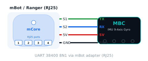
Get the MakeBlock edition (RJ25 plug) and plug it into an RJ25 port of mBot / Ranger / Orion / MegaPi; usable ports per board are listed in MakeBlock extension.
Setup
What you need
- Sensor: IMU 9-Axis Gyro (MakeBlock edition, different factory firmware from the other editions), plus an mBot adapter (to plug into an RJ25 port). SPIKE, EV3 and I2C editions cannot connect to a Makeblock board directly.
- Board: mBot (mCore), mBot Ranger (Auriga), Orion, Ultimate 2.0 (MegaPi), MegaPi Pro. mBot2 (CyberPi) has no RJ25 port and is not supported.
- Software: mBlock 5 for PC (Upload mode: the program is flashed to the board).
- Extension: MBC Pro Sensors v2.0.0 (for protocol v2 firmware shipped from 2026-10).
Install the software
- Install mBlock 5 for PC from the mBlock website.
- Open mBlock 5 and add your board (for example mBot) under "Devices" at the bottom left.
- Switch the mode toggle at the bottom right to Upload.
Make the software see the sensor
Add one extension and the MBC blocks appear:
- Get the v2.0.0 extension: once it is listed, search "MBC" in the mBlock 5 "Extension Center" and add it. Before it is listed (under review), advanced users can sign in to ext.mblock.cc with their own Makeblock account → My extensions → Import data, upload mbc_pro_sensors_2.0.0_import.mext (about 1 minute), then click "Download" to get a
.mext. - Drag the
.mextfile into the mBlock window. Six new categories appear: Pathfinder, Ranger, Controller, IMU gyro, Vision and MBC common. - Start the program with the board's start block (for example "when mBot starts up") and click "Upload" to flash it to the board.
- To open an example: "File → Open from your computer" and pick the
.mblockfile.
Important
The new extension (v2) only works with new firmware, and the legacy extension (v1.0.0) only with firmware from before 2026-10; their blocks are not compatible. Not sure which firmware you have? Drag in the v2 extension and read the "MBC common → protocol version" block: 2 means new firmware. The legacy extension is in the Downloads.
Wiring
Sensor → mBot adapter → the board's RJ25 port (UART 38400). The blocks ask for a port number; the extension maps it to the right pins for your board.
| Board | Usable ports | Notes |
|---|---|---|
| mBot (mCore) | 1, 2, 3, 4 | all four ports |
| mBot Ranger (Auriga) | 6 ~ 10 | 1 ~ 4 are red motor ports, 5 is the serial port |
| Orion | 3, 4, 6 | 1, 2 are red motor ports; 7, 8 are analog only |
| Ultimate 2.0 (MegaPi) | 6, 7, 8 | needs the RJ25 shield; 5 is the serial port |
| MegaPi Pro | 7, 8, 9, 10 | needs the RJ25 shield |
The examples on this page use mBot port 1; to use another port, change the port number on the blocks. On another board, replace "when mBot starts up" with that board's start block.
Note
The IMU MakeBlock edition is new in October 2026; before ordering, ask us on LINE to confirm the shipping version.
First test
- Start the program with "wait 1 second" so the sensor can boot; reading too early returns
-32768. - Check the wiring with the "MBC common → connection OK?" block, then look at the values.
- Upload example 1 on this page. If the number changes with the sensor, everything is connected.
FAQ
- "connection OK?" is false? Wrong port, the sensor is not the MakeBlock edition, or the firmware is legacy (use the v1 extension with old firmware).
- Reading
-32768? Nothing has been read since power-on: check the wiring; or this product has no such value. - The value never changes? Make sure the adapter is firmly in and the sensor light is on; "protocol version" reading 2 means communication works.
- Still stuck? Contact us on LINE with the board model, the port and the value of the "device ID" block.
Reading values
After adding the MBC Pro Sensors extension, find the blocks in the "IMU Gyro" category and pick the port the sensor is plugged into.
gyro 3D heading headingGyro3D
| Range | Meaning |
|---|---|
-32768~32767 ° |
heading from the 3D quaternion, degrees, 0 at boot/zero, accumulates past 360 (wraps at ±32767, ~91 turns) |
(IMU Gyro port [1 v] gyro 3D heading :: sensing)
Block returns gyro 3D heading(-32768~32767 °)。Host sends [01] → reply [lo][hi][01 ^ lo ^ hi], value = int16 little-endian.
fused heading headingFused
| Range | Meaning |
|---|---|
-32768~32767 ° |
3D gyro heading slowly corrected by the magnetometer, degrees, relative to the zero point; may exceed 360 |
(IMU Gyro port [1 v] fused heading :: sensing)
Block returns fused heading(-32768~32767 °)。Host sends [02] → reply [lo][hi][02 ^ lo ^ hi], value = int16 little-endian.
gyro 1D heading headingGyro1D
| Range | Meaning |
|---|---|
-32768~32767 ° |
heading integrated about the yaw axis only, degrees, 0 at boot/zero; may exceed 360 |
(IMU Gyro port [1 v] gyro 1D heading :: sensing)
Block returns gyro 1D heading(-32768~32767 °)。Host sends [03] → reply [lo][hi][03 ^ lo ^ hi], value = int16 little-endian.
magnetic heading headingMag
| Range | Meaning |
|---|---|
-32768~32767 ° |
tilt-compensated magnetometer heading, degrees, relative to the zero point |
(IMU Gyro port [1 v] magnetic heading :: sensing)
Block returns magnetic heading(-32768~32767 °)。Host sends [04] → reply [lo][hi][04 ^ lo ^ hi], value = int16 little-endian.
yaw rate yawRate
| Range | Meaning |
|---|---|
-32768~32767 0.1 dps |
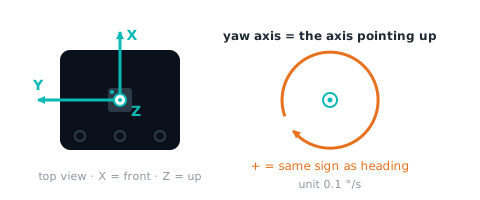
angular rate about the yaw axis (getYawAxis()), 0.1 deg/s, same sign as the heading |
(IMU Gyro port [1 v] yaw rate :: sensing)
Block returns yaw rate(-32768~32767 0.1 dps)。Host sends [05] → reply [lo][hi][05 ^ lo ^ hi], value = int16 little-endian.
pitch angle pitch
| Range | Meaning |
|---|---|
-90~+90 ° |
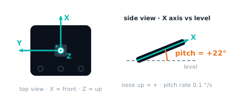
elevation of the board's printed X axis above horizontal: +90 pointing up, −90 pointing down, 0 level (from the gravity vector) |
(IMU Gyro port [1 v] pitch angle :: sensing)
Block returns pitch angle(-90~+90 °)。Host sends [06] → reply [lo][hi][06 ^ lo ^ hi], value = int16 little-endian.
pitch rate pitchRate
| Range | Meaning |
|---|---|
-32768~32767 0.1 dps |
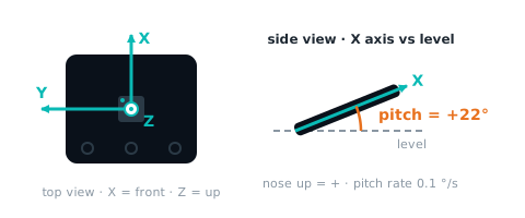
angular rate about the board's printed X axis, 0.1 °/s (right-hand rule, CCW seen from +X is positive); this is gyro X, not the derivative of 06 |
(IMU Gyro port [1 v] pitch rate :: sensing)
Block returns pitch rate(-32768~32767 0.1 dps)。Host sends [07] → reply [lo][hi][07 ^ lo ^ hi], value = int16 little-endian.
magnetometer trust magTrust
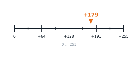
| Range | Meaning |
|---|---|
0~255 |
how much the fusion trusts the magnetometer, 0 |
(IMU Gyro port [1 v] magnetometer trust :: sensing)
Block returns magnetometer trust(0~255)。Host sends [08] → reply [lo][hi][08 ^ lo ^ hi], value = int16 little-endian.
magnetic disturbance magDisturb
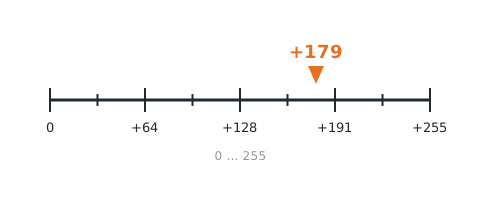
| Range | Meaning |
|---|---|
0~255 0.01° |
magnetic disturbance level 0~255 (degrees × 100, capped at 255) |
(IMU Gyro port [1 v] magnetic disturbance :: sensing)
Block returns magnetic disturbance(0~255 0.01°)。Host sends [09] → reply [lo][hi][09 ^ lo ^ hi], value = int16 little-endian.
face up upFace
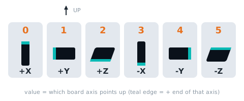
| Range | Meaning |
|---|---|
0~5 |
which axis points up: 0 +X, 1 +Y, 2 +Z, 3 −X, 4 −Y, 5 −Z (physical axes) |
(IMU Gyro port [1 v] face up :: sensing)
Block returns face up(0~5)。Host sends [0A] → reply [lo][hi][0A ^ lo ^ hi], value = int16 little-endian.
gyro axis 1~3 gyro
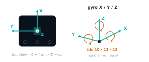
| Range | Meaning |
|---|---|
-32768~32767 0.1 dps |
10 X, 11 Y, 12 Z angular rate, 0.1 deg/s (physical axes, sign-corrected) |
(IMU Gyro port [1 v] gyro [axis] :: sensing)
Block returns gyro axis 1~3(-32768~32767 0.1 dps)。Host sends [10] → reply [lo][hi][10 ^ lo ^ hi], value = int16 little-endian; channel N uses id 0x10 + (N − 1).
accel axis 1~3 accel
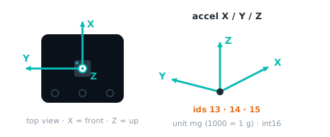
| Range | Meaning |
|---|---|
-32768~32767 mg |
13 X, 14 Y, 15 Z acceleration, mg (1000 = 1 g) |
(IMU Gyro port [1 v] accel [axis] :: sensing)
Block returns accel axis 1~3(-32768~32767 mg)。Host sends [13] → reply [lo][hi][13 ^ lo ^ hi], value = int16 little-endian; channel N uses id 0x13 + (N − 1).
mag axis 1~3 mag
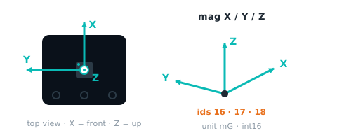
| Range | Meaning |
|---|---|
-32768~32767 mG |
16 X, 17 Y, 18 Z magnetic field, mG (milligauss) |
(IMU Gyro port [1 v] mag [axis] :: sensing)
Block returns mag axis 1~3(-32768~32767 mG)。Host sends [16] → reply [lo][hi][16 ^ lo ^ hi], value = int16 little-endian; channel N uses id 0x16 + (N − 1).
Not readable here:command status. Use Arduino / micro:bit for these.
Commands
zero heading zeroHeading
zero all four headings (zeroHeadings()); EV3 also accepts the stock gyro-reset WRITE 0x11
IMU Gyro port [1 v] zero heading :: sensing
Host sends [E0] → reply [00][00][E0] (ack), then it runs.
start accelerometer calibration accelCalStart
start accelerometer calibration (= v1 0x20=0x01); F3 b4 = 1 meanwhile; ignored during magnetometer calibration (0B state 3 rejected)
IMU Gyro port [1 v] start accelerometer calibration :: sensing
Host sends [E1] → reply [00][00][E1] (ack), then it runs; F3 bit4 = 1 while busy.
end accelerometer calibration accelCalEnd
finish accelerometer calibration and save to EEPROM (= v1 0x20=0x02); on success the mount axis is re-captured and headings are zeroed once the sensor is level and still (not immediately); rejected if not calibrating (0B state 3); failed check → 0B state 2
IMU Gyro port [1 v] end accelerometer calibration :: sensing
Host sends [E2] → reply [00][00][E2] (ack), then it runs.
start magnetometer calibration magCalStart
start magnetometer calibration (= v1 0x20=0x03); F3 b5 = 1 meanwhile; ignored if the magnetometer has failed (0B state 3)
IMU Gyro port [1 v] start magnetometer calibration :: sensing
Host sends [E3] → reply [00][00][E3] (ack), then it runs; F3 bit5 = 1 while busy.
end magnetometer calibration magCalEnd
finish magnetometer calibration and save to EEPROM (= v1 0x20=0x04); headings zeroed right away on success; rejected if not calibrating (0B state 3); failed check → 0B state 2
IMU Gyro port [1 v] end magnetometer calibration :: sensing
Host sends [E4] → reply [00][00][E4] (ack), then it runs.
update all values readAll
reads the whole value table into a cache (FD pack-all); reporter blocks within the next 10 ms use the cache instead of asking one by one
IMU Gyro port [1 v] update all values :: sensing
Not available here:set heading, north as zero, re-estimate gyro bias, re-capture mount axis, cancel calibration, heading correction, calibration factory reset
Examples
This page is for people who have never written a program: read the IMU Gyro on an mBot with mBlock 5 blocks. The 5 examples start with "turn the number into a sound" and work up to a robot that drives itself. Every example has a block picture, a downloadable project file and an Arduino sketch that does the same thing.
| Software | Who it suits | How to open the example file |
|---|---|---|
| 🟧 mBlock 5 desktop (blocks, Upload mode) + MBC Pro Sensors extension v2 | Schools, first time with an mBot | Download the .mblock → open mBlock 5 → "File → Open from your computer" → switch to "Upload" at the bottom right → "Upload" |
| 🔧 Arduino IDE (text code) | People who want to see what is behind the blocks, or write their own code | Download the .ino → install the Makeblock and MBC_Sensors libraries (see Makeblock extension) → board Arduino Uno → upload |
Important
- The sensor must be the Makeblock edition with the 2026-10 protocol v2 firmware, connected through the mBot socket board to an RJ25 port; use extension v2.0.0 (old firmware goes with the old v1 extension; they cannot be mixed).
- The board is the mBot (mCore). mBot Ranger, Orion and MegaPi work too: swap "when mBot starts up" for that board's hat block and use a port that board allows (see supported boards and ports); the mBot2 (CyberPi) has no RJ25 port and is not supported.
- mBlock 5 is shown here with its English block text; your copy may show the same blocks in another language.
Before you start
Sensor → mBot socket board → RJ25 port on the board (S1 = host TX, S2 = host RX, UART 38400).
- Install the extension: get the MBC Pro Sensors v2.0.0
.mextfrom Makeblock extension and drop it into the mBlock 5 window; add mBot under "Devices" (bottom left) and switch to "Upload" (bottom right). - Wiring: IMU gyro → mBot socket board → mBot port 2 (every example on this page uses this port; to use another, change the port number on the blocks).
- Let it boot first: every example starts with "wait 1 seconds" so the sensor can boot; reading too early gives -32768 (nothing received yet).
- Mount the IMU flat and firmly on the robot with the board's printed X axis along the forward direction; keep the robot still at power-on and when "zero heading" runs. Seen from above, turning right makes the heading grow (90° right = 90); it accumulates and never wraps back to 0.
Blocks used on this page
Each reporter block is one "value id" of the sensor's value table (the same ids as the Arduino I2C registers); the full block list is in Makeblock extension.
| Block | Returns | Meaning |
|---|---|---|
| IMU Gyro port [2] pitch angle | -90~+90 ° | elevation of the board's printed X axis above horizontal: +90 pointing up, −90 pointing down, 0 level (from the gravity vector) |
| IMU Gyro port [2] gyro 1D heading | -32768~32767 ° | heading integrated about the yaw axis only, degrees, 0 at boot/zero; may exceed 360 |
| IMU Gyro port [2] zero heading | — | zero all four headings (zeroHeadings()); EV3 also accepts the stock gyro-reset WRITE 0x11 |
Examples on this page
- Tilt changes the pitch
- The LED shows the heading
- Tilt drives one wheel
- Drive straight with correction
- Drive, turn 90°, drive again
Note
The
.mblockfiles are generated in the mBlock 5 save format and have not yet been opened in mBlock 5 for verification (pending the extension v2 release). If one will not open or shows blank blocks, check that extension v2 is loaded and the device is mBot, or rebuild it from the block picture below (under 5 minutes); you can also tell us on LINE.
Example 1: Tilt changes the pitch
What this example does: The mBot has no screen, so this example turns the "pitch angle" (nose up or down in degrees, 0 when flat) into a buzzer pitch: 440 Hz flat, higher nose-up, lower nose-down. Learn to "read the number" first.
What you need
- mBot (mCore board) + mBlock 5 desktop
- IMU Gyro (Makeblock edition) + mBot socket board
Wiring: IMU gyro → mBot socket board → mBot port 2. Mount it flat and firmly on the robot with the board's printed X axis along the robot's forward direction. Keep the robot still when the program starts.
Download
| mBlock 5 project | Equivalent Arduino sketch |
|---|---|
| ex01_tilt_tone.mblock | ex01_tilt_tone.ino |
mBlock blocks (just rebuild them like this)
when mBot starts up :: events hat
wait (1) seconds
forever
  play tone ((440) + ((IMU Gyro port [2 v] pitch angle :: #D9480F) * (4))) Hz for (0.1) seconds :: sound
end
🔧 Equivalent Arduino sketch (mBot)
// IMU Gyro × mBlock 5  Example 1: Tilt changes the pitch  (equivalent Arduino sketch for mBot)
// Wiring: IMU gyro → mBot socket board → mBot port 2. Mount it flat and firmly on the robot with the board's printed X axis along the robot's forward direction. Keep the robot still when the program starts.
// Does exactly what the mBlock block example does, for people who want to see "what is behind the blocks" or use the Arduino IDE.
// Libraries needed:
//   1. Makeblock (Arduino IDE Library Manager, search "Makeblock", or the copy inside the mBlock 5 install folder)
//   2. MBC_Sensors v2: the four files in src/ of the extension .mext (MBC_Sensors.h/.cpp, mbc_proto.h, mbc_ids.h),
//      put them in Documents/Arduino/libraries/MBC_Sensors/ and #include <MBC_Sensors.h> (https://mbc-pro-sensors.github.io/en/makeblock.html)
// Board: Arduino Uno (the mBot mCore is an Uno). After uploading, unplug USB and run on battery.

#include <MeMCore.h>            // mBot (mCore): motors, LED, buzzer
#include <SoftwareSerial.h>
#include <MBC_Sensors.h>        // MBC sensors v2 (the same library the mBlock extension uses)

MBCPort mbc_port2(2);           // sensor on mBot port 2
MeDCMotor motorL(9);           // left wheel (M1)
MeDCMotor motorR(10);          // right wheel (M2)
MeRGBLed rgbled(7, 2);         // on-board RGB LED (2 pixels)
MeBuzzer buzzer;               // on-board buzzer

// left / right wheel power -100~100 (positive = forward): the mBot left wheel is mounted mirrored, so M1 gets the negative value; % becomes PWM 0~255
void wheels(int l, int r) {
  l = constrain(l, -100, 100); r = constrain(r, -100, 100);
  motorL.run(-l * 255 / 100);
  motorR.run(r * 255 / 100);
}

void setup() {   // everything runs inside setup(), just like the program mBlock generates
  mbc_port2.begin();
  delay(1000);   // Wait 1 s for the sensor to boot
  while (1) {   // Repeat forever
    buzzer.tone((440 + (mbcRead(mbc_port2, 0x06) * 4)), 100);   // Pitch = 440 + pitch angle × 4 Hz, for 0.1 s
  }
}

void loop() {}   // nothing here: the blocks above never return
Step by step
- Wait 1 s for the sensor to boot
- Repeat forever
- Pitch = 440 + pitch angle × 4 Hz, for 0.1 s
What you should see: Robot flat: 440 Hz. Raise the nose slowly and the pitch rises (about 620 Hz at 45°); lower the nose and it drops.
FAQ
- No sound? → The buzzer is on the board and is not loud; listen closely, or change 0.1 s to 0.3 s.
- Nose up gives a lower note? → Normal: the sign depends on mounting. Mount the sensor rotated 180°, or change × 4 to × -4.
- The robot is still but the heading slowly drifts? → The robot must be completely still at power-on or zeroing. Put it down, unplug the sensor and plug it back in, then try again.
- Nothing happens, or the value stays at -32768? → Wrong port (every example on this page uses port 2), socket board not seated, or the sensor is not the Makeblock edition. Check with the "MBC common → connected?" block first; "protocol version" must read 2 for the new firmware (old firmware needs extension v1).
- Upload fails, or the blocks are blank? → Make sure the switch at the bottom right is in "Upload" mode, extension v2 has been dropped into mBlock, and the USB cable goes to the mBot board.
Example 2: The LED shows the heading
What this example does: Zero the heading at the start, then turn the robot by hand: more than 20° to the right → blue, more than 20° to the left → red, facing the original direction → green. The decision skeleton for "drive straight" and "turn 90°" later.
What you need
- mBot (mCore board) + mBlock 5 desktop
- IMU Gyro (Makeblock edition) + mBot socket board
Wiring: IMU gyro → mBot socket board → mBot port 2. Mount it flat and firmly on the robot with the board's printed X axis along the robot's forward direction. Keep the robot still when the program starts.
Download
| mBlock 5 project | Equivalent Arduino sketch |
|---|---|
| ex02_led_heading.mblock | ex02_led_heading.ino |
mBlock blocks (just rebuild them like this)
when mBot starts up :: events hat
wait (1) seconds
IMU Gyro port [2 v] zero heading :: #D9480F
forever
  if <(IMU Gyro port [2 v] gyro 1D heading :: #D9480F) > (20)> then
    LED [all v] colour red (0) green (0) blue (255) :: looks
  else
    if <(IMU Gyro port [2 v] gyro 1D heading :: #D9480F) < (-20)> then
      LED [all v] colour red (255) green (0) blue (0) :: looks
    else
      LED [all v] colour red (0) green (255) blue (0) :: looks
    end
  end
end
🔧 Equivalent Arduino sketch (mBot)
// IMU Gyro × mBlock 5  Example 2: The LED shows the heading  (equivalent Arduino sketch for mBot)
// Wiring: IMU gyro → mBot socket board → mBot port 2. Mount it flat and firmly on the robot with the board's printed X axis along the robot's forward direction. Keep the robot still when the program starts.
// Does exactly what the mBlock block example does, for people who want to see "what is behind the blocks" or use the Arduino IDE.
// Libraries needed:
//   1. Makeblock (Arduino IDE Library Manager, search "Makeblock", or the copy inside the mBlock 5 install folder)
//   2. MBC_Sensors v2: the four files in src/ of the extension .mext (MBC_Sensors.h/.cpp, mbc_proto.h, mbc_ids.h),
//      put them in Documents/Arduino/libraries/MBC_Sensors/ and #include <MBC_Sensors.h> (https://mbc-pro-sensors.github.io/en/makeblock.html)
// Board: Arduino Uno (the mBot mCore is an Uno). After uploading, unplug USB and run on battery.

#include <MeMCore.h>            // mBot (mCore): motors, LED, buzzer
#include <SoftwareSerial.h>
#include <MBC_Sensors.h>        // MBC sensors v2 (the same library the mBlock extension uses)

MBCPort mbc_port2(2);           // sensor on mBot port 2
MeDCMotor motorL(9);           // left wheel (M1)
MeDCMotor motorR(10);          // right wheel (M2)
MeRGBLed rgbled(7, 2);         // on-board RGB LED (2 pixels)
MeBuzzer buzzer;               // on-board buzzer

// left / right wheel power -100~100 (positive = forward): the mBot left wheel is mounted mirrored, so M1 gets the negative value; % becomes PWM 0~255
void wheels(int l, int r) {
  l = constrain(l, -100, 100); r = constrain(r, -100, 100);
  motorL.run(-l * 255 / 100);
  motorR.run(r * 255 / 100);
}

void setup() {   // everything runs inside setup(), just like the program mBlock generates
  mbc_port2.begin();
  delay(1000);   // Wait 1 s for the sensor to boot
  mbcWrite(mbc_port2, 0xE0);   // Zero the heading: the current direction becomes 0
  while (1) {   // Repeat forever
    if ((mbcRead(mbc_port2, 0x03) > 20)) {   // If the gyro 1D heading is greater than 20
      rgbled.setColor(0, 0, 0, 255); rgbled.show();   // Turned right more than 20°: blue
    } else {
      if ((mbcRead(mbc_port2, 0x03) < -20)) {   // Otherwise, if the gyro 1D heading is less than -20
        rgbled.setColor(0, 255, 0, 0); rgbled.show();   // Turned left more than 20°: red
      } else {
        rgbled.setColor(0, 0, 255, 0); rgbled.show();   // Facing the original direction: green
      }
    }
  }
}

void loop() {}   // nothing here: the blocks above never return
Step by step
- Wait 1 s for the sensor to boot
- Zero the heading: the current direction becomes 0
- Repeat forever
- If the gyro 1D heading is greater than 20
- Turned right more than 20°: blue
- otherwise:
- Otherwise, if the gyro 1D heading is less than -20
- Turned left more than 20°: red
- otherwise:
- Facing the original direction: green
- Otherwise, if the gyro 1D heading is less than -20
- If the gyro 1D heading is greater than 20
What you should see: Green at the start; turn the robot right and past 20° it goes blue; back again green; left past 20° red. A full turn comes back as 360, not 0, so it stays blue.
FAQ
- Turning right gives red? → The sensor is mounted upside down. Flip it, or swap 20 and -20 in the program.
- The robot is still but the heading slowly drifts? → The robot must be completely still at power-on or zeroing. Put it down, unplug the sensor and plug it back in, then try again.
- Nothing happens, or the value stays at -32768? → Wrong port (every example on this page uses port 2), socket board not seated, or the sensor is not the Makeblock edition. Check with the "MBC common → connected?" block first; "protocol version" must read 2 for the new firmware (old firmware needs extension v1).
- Upload fails, or the blocks are blank? → Make sure the switch at the bottom right is in "Upload" mode, extension v2 has been dropped into mBlock, and the USB cable goes to the mBot board.
Example 3: Tilt drives one wheel
What this example does: Use "pitch angle × 2" directly as the left wheel power: nose up → forward, nose down → reverse, flat → still; the more tilt, the faster. Prop the robot up to watch.
What you need
- mBot (mCore board) + mBlock 5 desktop
- mBot two-wheel robot (left wheel on M1, right wheel on M2, as shipped)
- IMU Gyro (Makeblock edition) + mBot socket board
Wiring: IMU gyro → mBot socket board → mBot port 2. Mount it flat and firmly on the robot with the board's printed X axis along the robot's forward direction. Keep the robot still when the program starts.
Download
| mBlock 5 project | Equivalent Arduino sketch |
|---|---|
| ex03_tilt_one_wheel.mblock | ex03_tilt_one_wheel.ino |
mBlock blocks (just rebuild them like this)
when mBot starts up :: events hat
wait (1) seconds
forever
  left wheel power ((IMU Gyro port [2 v] pitch angle :: #D9480F) * (2)) %, right wheel power (0) % :: motion
end
🔧 Equivalent Arduino sketch (mBot)
// IMU Gyro × mBlock 5  Example 3: Tilt drives one wheel  (equivalent Arduino sketch for mBot)
// Wiring: IMU gyro → mBot socket board → mBot port 2. Mount it flat and firmly on the robot with the board's printed X axis along the robot's forward direction. Keep the robot still when the program starts.
// Does exactly what the mBlock block example does, for people who want to see "what is behind the blocks" or use the Arduino IDE.
// Libraries needed:
//   1. Makeblock (Arduino IDE Library Manager, search "Makeblock", or the copy inside the mBlock 5 install folder)
//   2. MBC_Sensors v2: the four files in src/ of the extension .mext (MBC_Sensors.h/.cpp, mbc_proto.h, mbc_ids.h),
//      put them in Documents/Arduino/libraries/MBC_Sensors/ and #include <MBC_Sensors.h> (https://mbc-pro-sensors.github.io/en/makeblock.html)
// Board: Arduino Uno (the mBot mCore is an Uno). After uploading, unplug USB and run on battery.

#include <MeMCore.h>            // mBot (mCore): motors, LED, buzzer
#include <SoftwareSerial.h>
#include <MBC_Sensors.h>        // MBC sensors v2 (the same library the mBlock extension uses)

MBCPort mbc_port2(2);           // sensor on mBot port 2
MeDCMotor motorL(9);           // left wheel (M1)
MeDCMotor motorR(10);          // right wheel (M2)
MeRGBLed rgbled(7, 2);         // on-board RGB LED (2 pixels)
MeBuzzer buzzer;               // on-board buzzer

// left / right wheel power -100~100 (positive = forward): the mBot left wheel is mounted mirrored, so M1 gets the negative value; % becomes PWM 0~255
void wheels(int l, int r) {
  l = constrain(l, -100, 100); r = constrain(r, -100, 100);
  motorL.run(-l * 255 / 100);
  motorR.run(r * 255 / 100);
}

void setup() {   // everything runs inside setup(), just like the program mBlock generates
  mbc_port2.begin();
  delay(1000);   // Wait 1 s for the sensor to boot
  while (1) {   // Repeat forever
    wheels((mbcRead(mbc_port2, 0x06) * 2), 0);   // Left wheel power = pitch angle × 2, right wheel 0
  }
}

void loop() {}   // nothing here: the blocks above never return
Step by step
- Wait 1 s for the sensor to boot
- Repeat forever
- Left wheel power = pitch angle × 2, right wheel 0
What you should see: Flat: the left wheel is still; nose up 30° → the wheel runs forward at power 60; nose down → reverse.
FAQ
- The robot turns the wrong way and gets worse? → Swap the "+" and "−" (or swap the left and right wheel powers). The mBot ships with the left wheel on M1 and the right on M2; check your own wiring.
- The wheel creeps when flat? → The pitch is not always exactly 0. Add "if the absolute value is below 3 then power 0".
- The robot is still but the heading slowly drifts? → The robot must be completely still at power-on or zeroing. Put it down, unplug the sensor and plug it back in, then try again.
- Nothing happens, or the value stays at -32768? → Wrong port (every example on this page uses port 2), socket board not seated, or the sensor is not the Makeblock edition. Check with the "MBC common → connected?" block first; "protocol version" must read 2 for the new firmware (old firmware needs extension v1).
- Upload fails, or the blocks are blank? → Make sure the switch at the bottom right is in "Upload" mode, extension v2 has been dropped into mBlock, and the USB cable goes to the mBot board.
Example 4: Drive straight with correction
What this example does: Two wheels never run at exactly the same speed, so a robot drifts. Zero the heading, then use "heading × 2" as the correction: drifting right (heading grows) → left wheel slower, right wheel faster, pulling the nose back.
What you need
- mBot (mCore board) + mBlock 5 desktop
- mBot two-wheel robot (left wheel on M1, right wheel on M2, as shipped)
- IMU Gyro (Makeblock edition) + mBot socket board
Wiring: IMU gyro → mBot socket board → mBot port 2. Mount it flat and firmly on the robot with the board's printed X axis along the robot's forward direction. Keep the robot still when the program starts.
Download
| mBlock 5 project | Equivalent Arduino sketch |
|---|---|
| ex04_drive_straight.mblock | ex04_drive_straight.ino |
mBlock blocks (just rebuild them like this)
when mBot starts up :: events hat
wait (1) seconds
IMU Gyro port [2 v] zero heading :: #D9480F
forever
  set [fix v] to ((IMU Gyro port [2 v] gyro 1D heading :: #D9480F) * (2))
  left wheel power ((40) - (fix)) %, right wheel power ((40) + (fix)) % :: motion
end
🔧 Equivalent Arduino sketch (mBot)
// IMU Gyro × mBlock 5  Example 4: Drive straight with correction  (equivalent Arduino sketch for mBot)
// Wiring: IMU gyro → mBot socket board → mBot port 2. Mount it flat and firmly on the robot with the board's printed X axis along the robot's forward direction. Keep the robot still when the program starts.
// Does exactly what the mBlock block example does, for people who want to see "what is behind the blocks" or use the Arduino IDE.
// Libraries needed:
//   1. Makeblock (Arduino IDE Library Manager, search "Makeblock", or the copy inside the mBlock 5 install folder)
//   2. MBC_Sensors v2: the four files in src/ of the extension .mext (MBC_Sensors.h/.cpp, mbc_proto.h, mbc_ids.h),
//      put them in Documents/Arduino/libraries/MBC_Sensors/ and #include <MBC_Sensors.h> (https://mbc-pro-sensors.github.io/en/makeblock.html)
// Board: Arduino Uno (the mBot mCore is an Uno). After uploading, unplug USB and run on battery.

#include <MeMCore.h>            // mBot (mCore): motors, LED, buzzer
#include <SoftwareSerial.h>
#include <MBC_Sensors.h>        // MBC sensors v2 (the same library the mBlock extension uses)

MBCPort mbc_port2(2);           // sensor on mBot port 2
MeDCMotor motorL(9);           // left wheel (M1)
MeDCMotor motorR(10);          // right wheel (M2)
MeRGBLed rgbled(7, 2);         // on-board RGB LED (2 pixels)
MeBuzzer buzzer;               // on-board buzzer
float fix = 0;                // variable:fix

// left / right wheel power -100~100 (positive = forward): the mBot left wheel is mounted mirrored, so M1 gets the negative value; % becomes PWM 0~255
void wheels(int l, int r) {
  l = constrain(l, -100, 100); r = constrain(r, -100, 100);
  motorL.run(-l * 255 / 100);
  motorR.run(r * 255 / 100);
}

void setup() {   // everything runs inside setup(), just like the program mBlock generates
  mbc_port2.begin();
  delay(1000);   // Wait 1 s for the sensor to boot
  mbcWrite(mbc_port2, 0xE0);   // Zero the heading: the current direction becomes 0
  while (1) {   // Repeat forever
    fix = (mbcRead(mbc_port2, 0x03) * 2);   // fix = gyro 1D heading × 2
    wheels((40 - fix), (40 + fix));   // Left = 40 − fix, right = 40 + fix: drifting right (positive heading) → left wheel slow, right wheel fast
  }
}

void loop() {}   // nothing here: the blocks above never return
Step by step
- Wait 1 s for the sensor to boot
- Zero the heading: the current direction becomes 0
- Repeat forever
- fix = gyro 1D heading × 2
- Left = 40 − fix, right = 40 + fix: drifting right (positive heading) → left wheel slow, right wheel fast
What you should see: The robot drives straight; push the nose off course by hand and it turns back to the original direction and carries on.
FAQ
- It drifts more and more, even spins? → The correction is reversed (sensor mounted upside down): swap "40 − fix" and "40 + fix".
- It shakes left and right? → Lower × 2 (e.g. × 1).
- The robot is still but the heading slowly drifts? → The robot must be completely still at power-on or zeroing. Put it down, unplug the sensor and plug it back in, then try again.
- Nothing happens, or the value stays at -32768? → Wrong port (every example on this page uses port 2), socket board not seated, or the sensor is not the Makeblock edition. Check with the "MBC common → connected?" block first; "protocol version" must read 2 for the new firmware (old firmware needs extension v1).
- Upload fails, or the blocks are blank? → Make sure the switch at the bottom right is in "Upload" mode, extension v2 has been dropped into mBlock, and the USB cable goes to the mBot board.
Example 5: Drive, turn 90°, drive again
What this example does: A classic competition move: drive 2 s → spin right until the heading reaches 90° → beep → drive 2 s more. Turning by gyro is far more accurate than "turn for N seconds": "wait until heading > 88" waits for the turn (2° left for braking). No "forever" here; it stops when done.
What you need
- mBot (mCore board) + mBlock 5 desktop
- mBot two-wheel robot (left wheel on M1, right wheel on M2, as shipped)
- IMU Gyro (Makeblock edition) + mBot socket board
Wiring: IMU gyro → mBot socket board → mBot port 2. Mount it flat and firmly on the robot with the board's printed X axis along the robot's forward direction. Keep the robot still when the program starts.
Download
| mBlock 5 project | Equivalent Arduino sketch |
|---|---|
| ex05_turn_90.mblock | ex05_turn_90.ino |
mBlock blocks (just rebuild them like this)
when mBot starts up :: events hat
wait (1) seconds
IMU Gyro port [2 v] zero heading :: #D9480F
left wheel power (40) %, right wheel power (40) % :: motion
wait (2) seconds
stop moving :: motion
wait (0.5) seconds
IMU Gyro port [2 v] zero heading :: #D9480F
left wheel power (25) %, right wheel power (-25) % :: motion
wait until <(IMU Gyro port [2 v] gyro 1D heading :: #D9480F) > (88)>
stop moving :: motion
play tone (880) Hz for (0.3) seconds :: sound
left wheel power (40) %, right wheel power (40) % :: motion
wait (2) seconds
stop moving :: motion
🔧 Equivalent Arduino sketch (mBot)
// IMU Gyro × mBlock 5  Example 5: Drive, turn 90°, drive again  (equivalent Arduino sketch for mBot)
// Wiring: IMU gyro → mBot socket board → mBot port 2. Mount it flat and firmly on the robot with the board's printed X axis along the robot's forward direction. Keep the robot still when the program starts.
// Does exactly what the mBlock block example does, for people who want to see "what is behind the blocks" or use the Arduino IDE.
// Libraries needed:
//   1. Makeblock (Arduino IDE Library Manager, search "Makeblock", or the copy inside the mBlock 5 install folder)
//   2. MBC_Sensors v2: the four files in src/ of the extension .mext (MBC_Sensors.h/.cpp, mbc_proto.h, mbc_ids.h),
//      put them in Documents/Arduino/libraries/MBC_Sensors/ and #include <MBC_Sensors.h> (https://mbc-pro-sensors.github.io/en/makeblock.html)
// Board: Arduino Uno (the mBot mCore is an Uno). After uploading, unplug USB and run on battery.

#include <MeMCore.h>            // mBot (mCore): motors, LED, buzzer
#include <SoftwareSerial.h>
#include <MBC_Sensors.h>        // MBC sensors v2 (the same library the mBlock extension uses)

MBCPort mbc_port2(2);           // sensor on mBot port 2
MeDCMotor motorL(9);           // left wheel (M1)
MeDCMotor motorR(10);          // right wheel (M2)
MeRGBLed rgbled(7, 2);         // on-board RGB LED (2 pixels)
MeBuzzer buzzer;               // on-board buzzer

// left / right wheel power -100~100 (positive = forward): the mBot left wheel is mounted mirrored, so M1 gets the negative value; % becomes PWM 0~255
void wheels(int l, int r) {
  l = constrain(l, -100, 100); r = constrain(r, -100, 100);
  motorL.run(-l * 255 / 100);
  motorR.run(r * 255 / 100);
}

void setup() {   // everything runs inside setup(), just like the program mBlock generates
  mbc_port2.begin();
  delay(1000);   // Wait 1 s for the sensor to boot
  mbcWrite(mbc_port2, 0xE0);   // Zero the heading: the current direction becomes 0
  wheels(40, 40);   // Drive straight
  delay(2000);   // For 2 s
  wheels(0, 0);   // Stop
  delay(500);   // Wait 0.5 s for the robot to settle
  mbcWrite(mbc_port2, 0xE0);   // Zero the heading: the current direction becomes 0
  wheels(25, -25);   // Left wheel forward, right wheel back: spin right (slower is more accurate)
  while (!(mbcRead(mbc_port2, 0x03) > 88)) delay(5);   // Wait until the heading is greater than 88°
  wheels(0, 0);   // At 90°: stop
  buzzer.tone(880, 300);   // Beep
  wheels(40, 40);   // Drive straight again
  delay(2000);   // For 2 s
  wheels(0, 0);   // Stop
}

void loop() {}   // nothing here: the blocks above never return
Step by step
- Wait 1 s for the sensor to boot
- Zero the heading: the current direction becomes 0
- Drive straight
- For 2 s
- Stop
- Wait 0.5 s for the robot to settle
- Zero the heading: the current direction becomes 0
- Left wheel forward, right wheel back: spin right (slower is more accurate)
- Wait until the heading is greater than 88°
- At 90°: stop
- Beep
- Drive straight again
- For 2 s
- Stop
What you should see: The robot drives 2 s, spins right about 90°, beeps, drives 2 s more and stops: an L shape.
FAQ
- It always overshoots by a few degrees? → Change 88 to 85, or lower the spin power 25.
- It spins forever? → The heading does not grow when turning right (sensor upside down): change "25, -25" to "-25, 25".
- The robot is still but the heading slowly drifts? → The robot must be completely still at power-on or zeroing. Put it down, unplug the sensor and plug it back in, then try again.
- Nothing happens, or the value stays at -32768? → Wrong port (every example on this page uses port 2), socket board not seated, or the sensor is not the Makeblock edition. Check with the "MBC common → connected?" block first; "protocol version" must read 2 for the new firmware (old firmware needs extension v1).
- Upload fails, or the blocks are blank? → Make sure the switch at the bottom right is in "Upload" mode, extension v2 has been dropped into mBlock, and the USB cable goes to the mBot board.
Next steps
- All IMU gyro blocks and the usable ports per board: Makeblock extension; this product's block table: IMU Gyro × mBlock 5
- The same ideas on LEGO: EV3 beginner examples
- Arduino straight to the sensor (I2C edition, no mBot): Arduino examples
More questions
- Blocks keep returning 0? Check the port in the block matches the real port and that the program was uploaded to the board.
- Does the old extension still work? Sensors shipped before 2026-10 use the legacy v1.0.0 extension; old and new blocks are not compatible.
Still stuck? Contact us with your software and a screenshot of the program.
Downloads
- MBC_Pro_Sensors_mBlock5_v2.2.0_import.mext
- MBC_Pro_Sensors_mBlock5_v2.1.0_import.mext
- MBC_Pro_Sensors_mBlock5_v2.0.0_import.mext
- MBC_Pro_Sensors_mBlock5_v1.0.0.mext (legacy, units shipped before 2026-10)
- Download centre (libraries, firmware, catalogue for every product)
Sources
- Host and software list:
_build/guides.json - Values and commands:
_build/protocol/imu.json(single source of truth) - Setup:
_build/guides/software/mblock-mblock5.en.md、_build/guides/product/imu/mblock-mblock5.en.md - Examples:
sensors/imu/mblock-examples.md