
🟧 micro:bit Examples: IMU Gyro
Back to IMU Gyro × micro:bit | Product page | Reference
This page is for people who have never written code. The 5 examples start with "show a value on the LEDs" and build up to "drive a car". Everything is written for the MakeCode web editor with the MBC extension pxt-mbc-sensors v2: switch to JavaScript, paste an example and it runs; switch back to Blocks to see which blocks it becomes.
Important
- Extension pxt-mbc-sensors v2 has not been verified on hardware yet. Every example on this page compiles with the MakeCode CLI (once for V1, once for V2); value directions, ready times and power are still to be confirmed on a real board, see "to be tested" in the hardware checklist below.
- Use the Universal I2C edition of the product. The SPIKE and EV3 editions have different firmware and cannot be read by a micro:bit.
Software
| Editor | micro:bit V1 | micro:bit V2 | How |
|---|---|---|---|
| MakeCode web editor (makecode.microbit.org, Blocks / JavaScript) | ✔ (less memory, but every example here fits) | ✔ | New Project → gear → Extensions → paste https://github.com/contactmbcrobot/pxt-mbc-sensors → switch to JavaScript (top) → paste the example → Download the .hex and drag it onto the MICROBIT drive |
| MakeCode offline app (Windows / Mac) | ✔ | ✔ | Same; adding the extension the first time needs internet |
| Python Editor (MicroPython) | — | — | no MBC module yet |
- Sound: V2 has a built-in speaker; a V1 needs a buzzer or headphones on P0.
- Servos / motors: the examples use
pins.servoWritePin: one 9 g servo (SG90) on P1; for driving, two continuous-rotation servos (e.g. FS90R), left wheel P1, right wheel P2. Always power servos from an external 4.8–6 V battery pack whose − is joined to the micro:bit GND (common ground); never drive servos from the micro:bit 3V pin. - Block names: with the editor language set to English the blocks read as in the tables below; the tables also give the JavaScript call.
Before you start: hardware checklist (to be tested)
The micro:bit is a 3.3 V board. Each check must pass before an MBC product is connected; "to be tested" marks items extension v2 has not yet confirmed on real hardware.
| Check | This product | Status |
|---|---|---|
| Voltage | MBC products use 3.3 V I2C levels: connect straight to P19 / P20, no level shifter | ✔ |
| Power | about 20 mA, so the micro:bit 3V pin (limit about 90 mA on V1, 190 mA on V2) may do | to be tested |
| I2C pull-ups | the micro:bit already has 4.7 kΩ; if the product also has pull-ups, check the low level stays ≤ 0.3×VDD | to be tested |
| Clock stretching | the STM32 slave stretches the clock by default; the V2 (nRF52833) has a known issue with stretching, test on V1 and V2 | to be tested |
| Address clash | factory address 0x6A, different from every other MBC product, so it can share the bus with the line follower, ranger and gamepad as it is | — |
| Ready time | ready (F3 b0) about 2 s after power-on; keep the board still and flat at power-on and when zeroing, or the heading drifts | to be tested |
If you read nothing: check the wiring (SDA = P20, SCL = P19) → the external power → whether the "device at … is ready" block (Device group, advanced) returns true.
Wiring (the same for every example)
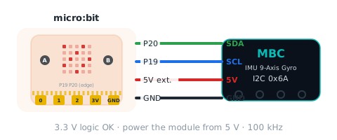
| Sensor | micro:bit |
|---|---|
| SDA | P20 |
| SCL | P19 |
| VCC | 3V (or external 5 V) |
| GND | GND (the servo battery − goes here too) |
The values used on this page
Headings are in degrees, 0 at power-on or after zeroing, growing when turning right, shrinking when turning left, and they keep accumulating past a full turn (no wrap at 360). The "fused" heading = gyro + magnetometer, the steadiest over time.
| Block | JavaScript | Range | Meaning | Used in |
|---|---|---|---|---|
| IMU heading fused (°) | mbc.imuHeading(MbcImuHeading.Fused) |
−32768~32767 | current heading, 0 = direction when zeroed, right = positive | 1, 3, 4, 5 |
| IMU zero heading | mbc.imuZeroHeading() |
命令 E0 | make the current direction 0 | 1, 2, 3, 4, 5 |
| IMU pitch (°) | mbc.imuPitch() |
−90~+90 | nose up / down in degrees | 2 |
| on IMU turned by … ° | mbc.onImuTurned(90, ...) |
事件 | fires each time the fused heading has changed by that many degrees | 2 |
| IMU is still | mbc.imuFlag(MbcImuFlag.Still) |
true / false | status bit 1: the board is not moving | 2 |
| wait for device at … ready | mbc.waitReady(mbc.ADDR_IMU, 3000) |
true / false | waits up to 3 s, true once the IMU is initialised (Advanced → Device) | 1 |
Example 1: Electronic compass
What this example does: Turn the micro:bit and the IMU together and the LED arrow turns the other way, always pointing where "front" was at power-on. Press A to show the heading, B to make the current direction 0.
What you need
- micro:bit V1 or V2 + USB cable
- IMU Gyro (Universal I2C edition) + 4-pin cable
- both boards fixed to one piece of cardboard
Wiring: As in the wiring table above: SDA → P20, SCL → P19, VCC → 3V, GND → GND.
Download: ex01_compass.ts (right-click, save) → MakeCode New Project → gear → Extensions → paste https://github.com/contactmbcrobot/pxt-mbc-sensors → switch to JavaScript (top) → select all, delete, paste the file → Download and drag the .hex onto the MICROBIT drive.
Code
// IMU × micro:bit example 1: electronic compass (the arrow keeps pointing where 'front' was at power-on)
// What it does: turn the micro:bit and the IMU together and the LED arrow turns the other way, always pointing at the original front. Press A to show the heading, B to make the current direction 0.
// Wiring: IMU SDA → P20, SCL → P19, VCC → 3V (or external 5 V), GND → GND.
// Setup: MakeCode new project → Extensions → paste https://github.com/contactmbcrobot/pxt-mbc-sensors → switch to JavaScript, paste this whole file → download to the micro:bit. Keep the IMU flat and still for 2 s after power-on.
// You see: tick at power-on, arrow up; turn right 90° → arrow points left; 180° → arrow down; turn back → arrow up.

const ARROWS = [ArrowNames.North, ArrowNames.NorthEast, ArrowNames.East, ArrowNames.SouthEast,
    ArrowNames.South, ArrowNames.SouthWest, ArrowNames.West, ArrowNames.NorthWest]   // 8 directions clockwise
let busy = false

if (mbc.waitReady(mbc.ADDR_IMU, 3000)) {
    basic.showIcon(IconNames.Yes)
} else {
    basic.showIcon(IconNames.No)                          // no answer: check P19 / P20 and power
}
mbc.imuZeroHeading()                                      // current direction = 0°

basic.forever(function () {
    if (busy) {
        basic.pause(100)
        return
    }
    let h = mbc.imuHeading(MbcImuHeading.Fused)           // degrees, grows turning right, shrinks turning left, may exceed 360
    let a = ((h % 360) + 360) % 360                       // fold to 0..359
    let idx = Math.round(a / 45) % 8                      // how many 45° steps turned
    basic.showArrow(ARROWS[(8 - idx) % 8], 0)             // the arrow points the opposite way, back to the original front
    basic.pause(50)
})

input.onButtonPressed(Button.A, function () {
    busy = true
    basic.showNumber(mbc.imuHeading(MbcImuHeading.Fused))
    busy = false
})
input.onButtonPressed(Button.B, function () {
    mbc.imuZeroHeading()
})
Step by step
ARROWS: 8 arrows clockwise starting from up.- After
mbc.waitReady(mbc.ADDR_IMU, 3000)ticks,mbc.imuZeroHeading(): the current direction = 0°. forever:h = mbc.imuHeading(Fused);a = ((h % 360) + 360) % 360folds it into 0..359 (negative values too).idx = Math.round(a / 45) % 8: how many 45° steps turned.ARROWS[(8 − idx) % 8]: the board turned right by idx steps, so the original front is idx steps to the left; the arrow takes the opposite direction.- A: show the heading; B: zero.
What you should see
- Power-on (board still): tick, arrow up.
- Turn right 90°: arrow points left; A shows about 90.
- 180°: arrow down. Back: up.
- Press B: whichever way you face, the arrow becomes up.
FAQ
- The number creeps although it is not moving? → Gyro drift. Keep the board still at power-on; leave it 10 s to self-calibrate, or press B to zero.
- The arrow turns with the board instead of against it? → Change
(8 − idx) % 8toidxfor the other kind of compass. - An X right at power-on (sensor not found)? → Check SDA = P20 and SCL = P19 are not swapped, that the external power is on, and with crocodile clips that no clip touches the neighbouring pad.
- All zeros in the simulator? → Normal. The MakeCode simulator has no real I2C, every read is 0; download to the micro:bit to see real values.
- No sound on a V1? → The V1 has no speaker; connect a buzzer or headphones between P0 and GND.
Example 2: Turn counter + tilt alarm
What this example does: Every 90° turned → a beep and the count goes up (event block); tilted more than 20° nose up / down → sad face + low alarm; still → asleep face, moving → happy. Press B to reset.
What you need
- Everything from example 1
- On a V1 also a buzzer or headphones on P0
Wiring: Same as example 1.
Download: ex02_turn_alarm.ts (right-click, save) → MakeCode New Project → gear → Extensions → paste https://github.com/contactmbcrobot/pxt-mbc-sensors → switch to JavaScript (top) → select all, delete, paste the file → Download and drag the .hex onto the MICROBIT drive.
Code
// IMU × micro:bit example 2: turn counter + tilt alarm
// What it does: every 90° turned → a beep and the count goes up by 1; tilted more than 20° nose up / down → sad face + low alarm; still → asleep face, moving → happy. Press B to reset.
// Wiring: IMU SDA → P20, SCL → P19, VCC → 3V, GND → GND. On a V1 connect a buzzer or headphones to P0 for sound (V2 has a speaker).
// Setup: extension and paste steps as in example 1.
// You see: turn it slowly through a full circle on the table → 4 beeps and 1 2 3 4; lift the front edge → sad face + alarm; leave it still → asleep face.

let turns = 0

mbc.imuZeroHeading()

mbc.onImuTurned(90, function () {                         // fires each time the fused heading has changed by another 90°
    turns += 1
    music.playTone(Note.C5, 150)
    basic.showNumber(turns)
})

input.onButtonPressed(Button.B, function () {
    turns = 0
    mbc.imuZeroHeading()
    basic.showNumber(0)
})

basic.forever(function () {
    let p = mbc.imuPitch()                                // pitch in degrees: nose up or down
    if (Math.abs(p) > 20) {
        basic.showIcon(IconNames.Sad, 0)
        music.playTone(Note.C, 200)                       // low alarm
    } else if (mbc.imuFlag(MbcImuFlag.Still)) {           // status bit 1: still
        basic.showIcon(IconNames.Asleep, 0)
    } else {
        basic.showIcon(IconNames.Happy, 0)
    }
    basic.pause(100)
})
Step by step
mbc.imuZeroHeading()zeroes first.mbc.onImuTurned(90, ...): runs once each time the fused heading has changed by another 90° →turns + 1,Note.C5, show the count.forever:p = mbc.imuPitch().Math.abs(p) > 20→ sad face + lowNote.C.- Otherwise
mbc.imuFlag(MbcImuFlag.Still)true → asleep face; false → happy. - B:
turns = 0, zero, show 0.
What you should see
- Turn it slowly through a full circle on the table: 4 beeps, 1 2 3 4.
- Lift the front edge more than 20°: sad face + alarm; flat again: stops.
- Leave it still for 1 s: asleep face; wave it: happy.
FAQ
- 5 beeps for one circle? → Overshoot when turning fast, or turning back counts too (both directions accumulate). It is a "change" event, direction does not matter.
- The tilt alarm never stops? → The IMU is not flat, or the mounting axis is not captured yet (status bit 2). Power on flat and try again.
Example 3: Stabilised turret (the servo keeps pointing the same way)
What this example does: A servo next to the IMU with an arrow on its arm: rotate the base and the servo counter-rotates so the arrow keeps pointing the original way (within ±90°). Press A to reset the reference direction.
What you need
- Everything from example 1
- one 9 g servo (SG90) with a paper arrow
- a 4.8–6 V battery pack and jumper wires
- a board that holds the micro:bit, the IMU and the servo together
Wiring: IMU as in example 1. Servo orange (signal) → P1, red → external 4.8–6 V battery +, brown → battery −, and run a second wire from battery − to micro:bit GND (common ground).
Download: ex03_stabilize_servo.ts (right-click, save) → MakeCode New Project → gear → Extensions → paste https://github.com/contactmbcrobot/pxt-mbc-sensors → switch to JavaScript (top) → select all, delete, paste the file → Download and drag the .hex onto the MICROBIT drive.
Code
// IMU × micro:bit example 3: stabilised turret (the servo keeps pointing the same way)
// What it does: a servo mounted next to the IMU with an arrow on top: rotate the base and the servo counter-rotates so the arrow keeps pointing the original way (within ±90°). Press A to reset the reference direction.
// Wiring: IMU SDA → P20, SCL → P19, VCC → 3V, GND → GND. Servo orange (signal) → P1, red → external 4.8–6 V battery +, brown → battery − joined to micro:bit GND.
// Setup: a 9 g servo (SG90) and a board that holds the micro:bit, the IMU and the servo together.
// You see: turn the base right by 45° → the servo turns left 45°, the arrow still points the same way; beyond 90° the servo hits its end stop.

mbc.imuZeroHeading()
basic.showIcon(IconNames.Yes)

basic.forever(function () {
    let h = mbc.imuHeading(MbcImuHeading.Fused)           // positive when turned right
    let angle = Math.constrain(90 - h, 0, 180)            // base turns right → servo turns left
    pins.servoWritePin(AnalogPin.P1, angle)
    basic.pause(20)
})

input.onButtonPressed(Button.A, function () {
    mbc.imuZeroHeading()                                  // the current direction becomes the new 0°
    basic.showIcon(IconNames.Yes, 0)
})
Step by step
mbc.imuZeroHeading(): current direction = 0.forever:h = fused heading(right = positive).angle = Math.constrain(90 − h, 0, 180): the base turned right by h, so the servo goes to 90 − h (h to the left) and the arrow still points the original way.pins.servoWritePin(AnalogPin.P1, angle)every 20 ms.- A: zero again; the current direction becomes the new reference.
What you should see
- Turn the base right 45°: the servo goes left 45°, the arrow stays put.
- Beyond 90°: the servo hits its end stop (0° or 180°).
- Press A: servo back to 90°, the current direction becomes the reference.
FAQ
- The servo turns with the base? → The servo is mounted the other way: change
90 − hto90 + h. - It slowly drifts? → Gyro drift; press A to zero. Leaving it still for 10 s lets it self-calibrate.
Example 4: Drive straight (gyro correction)
What this example does: Press A and the car drives forward; whenever it drifts, the heading steers it back, so it runs straight. Press B to stop. The LEDs show which way it corrects. The basic skill of every gyro robot.
What you need
- A two-wheel car: two continuous-rotation servos (e.g. FS90R) as wheels plus a caster
- the IMU flat on the car, printed arrow forward
- a 4.8–6 V battery pack
Wiring: IMU as in example 1, flat on the car with the printed arrow toward the front. Left continuous-rotation servo signal → P1, right → P2; both servo red wires to the 4.8–6 V battery pack +, brown to battery −, and battery − also to micro:bit GND.
Download: ex04_drive_straight.ts (right-click, save) → MakeCode New Project → gear → Extensions → paste https://github.com/contactmbcrobot/pxt-mbc-sensors → switch to JavaScript (top) → select all, delete, paste the file → Download and drag the .hex onto the MICROBIT drive.
Code
// IMU × micro:bit example 4: drive straight (gyro correction)
// What it does: press A and the car drives forward; whenever it drifts, the IMU heading steers it back, so it runs straight. Press B to stop. The LEDs show which way it is correcting.
// Wiring: IMU SDA → P20, SCL → P19, VCC → 3V, GND → GND. Left continuous-rotation servo signal → P1, right → P2; servos on a 4.8–6 V battery pack whose − is joined to micro:bit GND.
// Setup: a two-wheel car with the IMU flat on it (printed arrow facing forward).
// You see: after A the car drives straight; nudge the front sideways and it turns back to the original heading and carries on.

const KP = 2                                              // 1° off → 2% speed difference
let running = false

// left servo P1, right servo P2 (continuous rotation); left / right = −100..100, positive = forward
function drive(left: number, right: number): void {
    left = Math.constrain(left, -100, 100)
    right = Math.constrain(right, -100, 100)
    pins.servoWritePin(AnalogPin.P1, Math.round(90 + left * 0.9))    // 90 = stop, 180 = full forward, 0 = full reverse
    pins.servoWritePin(AnalogPin.P2, Math.round(90 - right * 0.9))   // the right servo is mounted mirrored, so subtract
}

input.onButtonPressed(Button.A, function () {
    mbc.imuZeroHeading()                                  // the starting direction = 0°
    running = true
    basic.showArrow(ArrowNames.North, 0)
})
input.onButtonPressed(Button.B, function () {
    running = false
    drive(0, 0)
    basic.showIcon(IconNames.No, 0)
})

basic.forever(function () {
    if (!running) {
        basic.pause(100)
        return
    }
    let h = mbc.imuHeading(MbcImuHeading.Fused)           // positive = the nose has drifted right
    let turn = Math.constrain(h * KP, -40, 40)
    drive(50 - turn, 50 + turn)                           // drifted right → left slower, right faster → steer back left
    if (turn > 5) {
        basic.showArrow(ArrowNames.NorthWest, 0)
    } else if (turn < -5) {
        basic.showArrow(ArrowNames.NorthEast, 0)
    } else {
        basic.showArrow(ArrowNames.North, 0)
    }
    basic.pause(20)
})
Step by step
function drive(left, right): left wheel P1, right wheel P2, −100..100, positive = forward; the right servo is mirrored so it subtracts.- A:
mbc.imuZeroHeading()makes the start direction 0,running = true; B: stop. forever:h = fused heading, positive = the nose drifted right.turn = Math.constrain(h × KP, −40, 40),KP = 2: 1° off → 2% difference.drive(50 − turn, 50 + turn): drifted right → left slower, right faster → steer back left. The arrow shows the correction.
What you should see
- Press A: the car runs straight, much straighter than without the gyro.
- Nudge the nose 30° sideways: the arrow tilts and the car turns back to its original heading.
- Press B: stop.
FAQ
- It wags left and right? → Change
KPfrom 2 to 1. - It corrects the wrong way (drifts more)? → The IMU is mounted backwards (arrow to the rear) or the servo signs are flipped. Run example 1 first and confirm the number grows when turning right.
Example 5: Drive a square (all together)
What this example does: Press A: drive straight for 1.5 s (gyro keeps it straight) → spin right exactly 90° (by heading, not by time) → repeat 4 times back to the start; the LEDs show which side. Press B to abort.
What you need
- The car from example 4
- about 1 m square of clear floor
Wiring: Same as example 4.
Download: ex05_square_path.ts (right-click, save) → MakeCode New Project → gear → Extensions → paste https://github.com/contactmbcrobot/pxt-mbc-sensors → switch to JavaScript (top) → select all, delete, paste the file → Download and drag the .hex onto the MICROBIT drive.
Code
// IMU × micro:bit example 5: drive a square (all together)
// What it does: press A: drive straight for 1.5 s (gyro keeps it straight) → spin right exactly 90° → repeat 4 times back to the start; the LEDs show which side it is on. Press B to abort.
// Wiring: as example 4 (IMU P19 / P20; left wheel P1, right wheel P2, servos on their own battery, common ground).
// Setup: the two-wheel car and about 1 m square of clear floor.
// You see: after A the car drives a square showing 1 2 3 4, then stops with a tick. Under- or overshooting corners → lower TURN_SPEED.

const SIDE_MS = 1500                                      // how long each side takes
const TURN_SPEED = 35
let running = false

// left servo P1, right servo P2 (continuous rotation); left / right = −100..100, positive = forward
function drive(left: number, right: number): void {
    left = Math.constrain(left, -100, 100)
    right = Math.constrain(right, -100, 100)
    pins.servoWritePin(AnalogPin.P1, Math.round(90 + left * 0.9))    // 90 = stop, 180 = full forward, 0 = full reverse
    pins.servoWritePin(AnalogPin.P2, Math.round(90 - right * 0.9))   // the right servo is mounted mirrored, so subtract
}

// drive straight for ms milliseconds, holding the heading target with the gyro
function straight(target: number, ms: number): void {
    let t0 = control.millis()
    while (running && control.millis() - t0 < ms) {
        let err = mbc.imuHeading(MbcImuHeading.Fused) - target
        let turn = Math.constrain(err * 2, -40, 40)
        drive(50 - turn, 50 + turn)
        basic.pause(20)
    }
}

// spin on the spot until the heading is within 3° of target
function turnTo(target: number): void {
    while (running) {
        let err = target - mbc.imuHeading(MbcImuHeading.Fused)   // positive = still need to turn right
        if (Math.abs(err) < 3) {
            break
        }
        let s = err > 0 ? TURN_SPEED : -TURN_SPEED
        drive(s, -s)                                      // left forward, right back = turn right
        basic.pause(20)
    }
    drive(0, 0)
    basic.pause(300)                                      // settle
}

input.onButtonPressed(Button.A, function () {
    if (running) {
        return
    }
    running = true
    mbc.imuZeroHeading()
    let target = 0
    for (let side = 1; side <= 4; side++) {
        basic.showNumber(side)
        straight(target, SIDE_MS)
        target += 90                                      // heading of the next side
        turnTo(target)
    }
    drive(0, 0)
    if (running) {
        basic.showIcon(IconNames.Yes)
    }
    running = false
})
input.onButtonPressed(Button.B, function () {
    running = false
    drive(0, 0)
    basic.showIcon(IconNames.No)
})
Step by step
straight(target, ms): drive for ms milliseconds, correcting with "heading − target" every 20 ms, as in example 4.turnTo(target):err = target − heading; stop when|err| < 3; otherwisedrive(s, −s)spins on the spot (positive err → right), then 0.3 s to settle.- A: zero,
target = 0;for side = 1..4: show the side →straight(target, 1500)→target += 90→turnTo(target). - After 4 sides
drive(0, 0)and a tick. - B:
running = false; thewhile (running)loops instraightandturnToexit at once.
What you should see
- Press A: shows 1, straight, right turn; 2, straight, right turn … after 4 sides a tick, back near the start.
- Every corner is 90° and errors do not add up (it watches the heading).
FAQ
- It overshoots and jitters at corners? → Change
TURN_SPEED35 to 25, or< 3to< 5. - Sides are not equal? → Sides are timed, so a sagging battery shortens them; use a line follower or encoders for accuracy.
- A triangle instead? →
for3 times andtarget += 120.
Next steps
- Every block, value and hardware note: IMU Gyro × micro:bit
- What each value id means: Reference
- Extension source and issues: https://github.com/contactmbcrobot/pxt-mbc-sensors