
IMU Gyro Sensor × micro:bit (MakeCode extension)
The universal I2C edition of the IMU Gyro Sensor works with BBC micro:bit V1 / V2 through the MakeCode extension pxt-mbc-sensors v2 (which speaks MBC I2C protocol v2). Installation and hardware notes (3.3 V, power): micro:bit overview.
SPIKEEV3Arduino I2CmBlockMATRIXmicro:bit
Important
Extension v2 is not yet verified on hardware; block names follow the published release: https://github.com/contactmbcrobot/pxt-mbc-sensors
Wiring
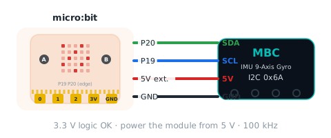
| Sensor | micro:bit |
|---|---|
| SDA(RX) | P20 |
| SCL(TX) | P19 |
| VCC | micro:bit 3V (external 5 V recommended on batteries) |
| GND | GND |
Reporter blocks
| Block | Returns | Id | Meaning |
|---|---|---|---|
| IMU heading [gyro 3D] (°) | -32768~32767 ° | 01 |
heading from the 3D quaternion, degrees, 0 at boot/zero, accumulates past 360 (wraps at ±32767, ~91 turns) |
| IMU heading [fused] (°) | -32768~32767 ° | 02 |
3D gyro heading slowly corrected by the magnetometer, degrees, relative to the zero point; may exceed 360 |
| IMU heading [gyro 1D] (°) | -32768~32767 ° | 03 |
heading integrated about the yaw axis only, degrees, 0 at boot/zero; may exceed 360 |
| IMU heading [magnetic] (°) | -32768~32767 ° | 04 |
tilt-compensated magnetometer heading, degrees, relative to the zero point |
| IMU turn rate (0.1 °/s) | -32768~32767 0.1 dps | 05 |
angular rate about the yaw axis (getYawAxis()), 0.1 deg/s, same sign as the heading |
| IMU pitch (°) | -90~+90 ° | 06 |
elevation of the board's printed X axis above horizontal: +90 pointing up, −90 pointing down, 0 level (from the gravity vector) |
| IMU pitch rate (0.1 °/s) | -32768~32767 0.1 dps | 07 |
angular rate about the board's printed X axis, 0.1 °/s (right-hand rule, CCW seen from +X is positive); this is gyro X, not the derivative of 06 |
| IMU magnetic trust | 0~255 | 08 |
how much the fusion trusts the magnetometer, 0 |
| IMU magnetic disturbance | 0~255 0.01° | 09 |
magnetic disturbance level 0~255 (degrees × 100, capped at 255) |
| IMU face up | 0~5 | 0A |
which axis points up: 0 +X, 1 +Y, 2 +Z, 3 −X, 4 −Y, 5 −Z (physical axes) |
| IMU [gyro (0.1 °/s)] axis [X / Y / Z] | -32768~32767 0.1 dps | 10~12 |
10 X, 11 Y, 12 Z angular rate, 0.1 deg/s (physical axes, sign-corrected) |
| IMU [accelerometer (mg)] axis [X / Y / Z] | -32768~32767 mg | 13~15 |
13 X, 14 Y, 15 Z acceleration, mg (1000 = 1 g) |
| IMU [magnetometer (mG)] axis [X / Y / Z] | -32768~32767 mG | 16~18 |
16 X, 17 Y, 18 Z magnetic field, mG (milligauss) |
More blocks (yes / no, events)
| Block | Related value |
|---|---|
| on IMU turned by 90 ° | 02 |
| IMU is [still] | 05 |
| IMU face up is [+Z] | 0A |
Command blocks
| Block | Id | Meaning |
|---|---|---|
| IMU zero heading | E0 |
zero all four headings (zeroHeadings()); EV3 also accepts the stock gyro-reset WRITE 0x11 |
| IMU calibration [accelerometer start] | E1 |
start accelerometer calibration (= v1 0x20=0x01); F3 b4 = 1 meanwhile; ignored during magnetometer calibration (0B state 3 rejected) |
| IMU calibration [accelerometer end] | E2 |
finish accelerometer calibration and save to EEPROM (= v1 0x20=0x02); on success the mount axis is re-captured and headings are zeroed once the sensor is level and still (not immediately); rejected if not calibrating (0B state 3); failed check → 0B state 2 |
| IMU calibration [magnetometer start] | E3 |
start magnetometer calibration (= v1 0x20=0x03); F3 b5 = 1 meanwhile; ignored if the magnetometer has failed (0B state 3) |
| IMU calibration [magnetometer end] | E4 |
finish magnetometer calibration and save to EEPROM (= v1 0x20=0x04); headings zeroed right away on success; rejected if not calibrating (0B state 3); failed check → 0B state 2 |
Status
| bit | Name | Meaning |
|---|---|---|
| b0 | ready (ready) |
always 1 |
| b1 | stationary (still) |
1 = sensor is stationary |
| b2 | mount axis captured (axisCaptured) |
1 = mounting orientation determined (headings zeroed once after first capture) |
| b3 | mount too tilted (mountTilted) |
1 = mounted too far from level |
| b4 | accel calibrating (accelCalibrating) |
1 between E1 and E2 |
| b5 | mag calibrating (magCalibrating) |
1 between E3 and E4 |
| b6 | fusion initialised (fusionInit) |
1 = fused heading is valid |
| b7 | mag auto-cal converged (magAutoCalDone) |
1 = magnetometer auto-calibration offsets have converged |
JavaScript
if (!(mbc.waitReady(0x6A, 3000))) {
    basic.showIcon(IconNames.No)   // nothing answers: check wiring and power
}
basic.forever(function () {
    basic.showNumber(mbc.imuHeading(MbcImuHeading.Gyro3D))   // gyro 3D heading
    basic.pause(100)
})
Sources and assumptions
Generated by _build/gen-reference.mjs from _build/protocol/imu.json (single source of truth, transcribed from the 2026-10-21 protocol decisions).
- hw0 = 1(共識 #6);EV3 模式 4 = [0x6A | 1<<8, 韌體主×100+次, 0, 0](格式 B 再補 2 個 0),模式 5 改送俯仰角速度(取代 #65 放的 ID)。
- EV3 鎖住模式 0/1/3 照盤點程式碼:0 = 陀螺 3D、1 = 融合航向、3 = [陀螺 1D, 磁力航向](INO:213 註解寫反,以程式為準)。
- 0x22 照 R4 版(出貨版)鎖住:命令 4
9 = 三個航向 +32768 的「低 byte 在前、高 byte 在後」;盤點檔分析的是主韌體(高在前),主韌體 #67 改成跟 R4 版逐 byte 相同。命令 1012 = 0;0x01、0x0A、0x0F、F1~F4 都觸發航向歸零(刻意,不動)。 - B-13:E1~E4 加速度計/磁力計校準開始/結束補回(v1 的 0x20 = 01/02/03/04),I2C 定案 §3 只列 E0。busyFlag:E1 → b4、E3 → b5。
- 俯仰角範圍定案沒寫(韌體尚無現成值,#67 用 atan2 新算),range 先填「°」不給 min/max,韌體做好後再補。
- 磁力信任度 08 = round(trust×255),磁場干擾度 09 = round(disturbance×100) 上限 255,朝上的面 0A = 軸號 + 3×負向:公式照盤點 I2C v1 0x34~0x36。
- 角速度 10
12 = round(dps×SIGN×10)、加速度 1315 = mm/s²×1000/9806.65、磁力 1618 = raw×SIGN×4/15:公式照盤點 I2C v1 0x220x24;mBlock 一併有(I2C 定案 §4 共用值表)。 - 主對話 2026-10-22:06 俯仰角範圍 −90~+90、07 = gyro X(照字面),取自 F5 韌體實作。
- The extension reads
Int16LEand pauses 2 ms after writing the id (D5); with no sensor answering, reporters return 0 and yes / no blocks return false.