
Controller PS4/PS5 × Arduino × Arduino IDE
Interactive tutorialArduino
First time? Try the interactive tutorial in your browser first, then follow the steps below with your hub.
This page covers Arduino IDE (C++) only: how to set it up for the Controller PS4/PS5 on Arduino / ESP32 / UNO R4 (I2C), how to read every value, the commands it supports and examples. Use the switcher above to change product, host or software.
Which edition and how to connect
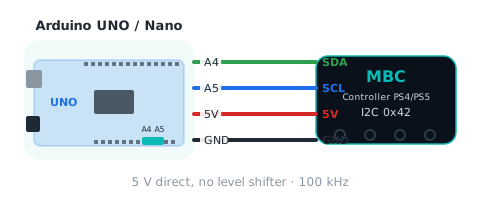
Get the Universal I2C edition (4 pins: 5V, GND, SDA, SCL), factory I2C address 0x42. UNO / Nano: A4 (SDA), A5 (SCL); UNO R4 and ESP32: the pins marked SDA / SCL.
Setup
What you need
- Sensor: Controller PS4/PS5 (Universal I2C edition) with its 4-wire cable. SPIKE and EV3 editions run different firmware and cannot connect to an Arduino directly.
- Board: Arduino UNO (or Nano) is the most common; Mega, UNO R4 and ESP32 also work.
- USB cable: the UNO uses a square (USB-B) cable; a Nano uses Mini USB or Type-C depending on the board. It must be a data cable; some cheap cables can only charge.
- Computer: Windows or Mac.
- Software: Arduino IDE (free).
Install the software
Tip
First time with Arduino? Start with First time with Arduino: from zero: in 15 minutes you install the software, upload a program and see the result.
- Download it from the official site: arduino.cc/en/software. Choose your computer system (on Windows, choose Windows Win 10 and newer).
- The download page asks if you want to donate. Click JUST DOWNLOAD to download right away.
- During setup, click Next each time. If it asks to install drivers, click Install every time.
- To change the language: File → Preferences → Language, then click OK and restart.
- For an ESP32, install the ESP32 board package first.
Make the software see the sensor
No library to install. Every example is a single .ino file; the small helper functions that read and write the sensor (such as mbcReadMany) are already inside it. Copy, paste, done.
- Connect the Arduino to the computer with the USB cable and choose your board (for example Arduino Uno) in the drop-down menu at the top of the IDE. The port is shown next to it, such as COM3 (on a Mac:
/dev/cu.usb…). - On the examples page, click Copy at the top right of the code box, or download the
.inofile. - File → New Sketch, delete everything in the new window and paste the code.
- Click → (Upload) at the top left. When "Done uploading" appears at the bottom, it worked.
The sensor talks I2C; its factory address is 0x42. Protocol details: MBC Universal I2C protocol.
Wiring
MBC Universal I2C sensors use only 4 wires: two for power (VCC, GND) and two for signals (SDA, SCL).
| Sensor | UNO / Nano | Mega | UNO R4 | ESP32 |
|---|---|---|---|---|
| VCC | 5V | 5V | 5V | 5V (VIN) |
| GND | GND | GND | GND | GND |
| SDA | A4 | 20 | A4 | GPIO 21 |
| SCL | A5 | 21 | A5 | GPIO 22 |
Important
- Unplug the USB cable before wiring. Connect the wires, check them once, then plug the USB cable back in.
- If the sensor cable is labelled TX / RX: TX goes to SCL, RX to SDA.
- The connector order differs a little between products. Always follow the labels printed on the sensor board.
- On the UNO, the top two unnumbered pins near the USB connector are also labelled SDA, SCL; they are the same as A4 and A5.
Pair the gamepad (first use or new gamepad)
- Connect the receiver and turn the controller on. Do not hold the receiver's button while plugging it in (that enters flashing mode and the receiver does nothing; release the button, unplug and replug).
- First use: a receiver that remembers no gamepad opens a 30-second pairing window at power-on (green LED blinking fast). To change gamepads, or if the 30 seconds are over: press the receiver's button (Reset) once; it forgets the old gamepad and opens 30 seconds again.
- Within those 30 seconds put the gamepad in pairing mode until its light bar flashes fast: PS4 hold SHARE + PS; PS5 hold Create + PS.
- Once connected, the receiver remembers this gamepad and will not connect to anyone else's. From then on, just press the gamepad's PS button after power-on.
| Receiver green LED | Meaning |
|---|---|
| Blinking fast | Waiting for a gamepad to pair |
| Steady on | No gamepad connected (press the PS button to reconnect) |
| Off | Gamepad connected |
Tip
At a competition, pair at your own table so no other team's gamepad is in pairing mode during the 30 seconds. Paired the wrong one? Press Reset and pair again.
Warning
With only ■ pressed, 16 buttons (id
01) =0x8000= -32768, exactly the same asMBC_NONEfor no answer. To detect "no answer", use the true / false returned bymbcReadMany, not a test for -32768:int16_t b; if (mbcReadMany(0x42, 0x01, 1, &b)) { … }; true means it was read, then use(uint16_t)bas the 16 buttons.
First test
- Upload example 1 on this page.
- Click the magnifying glass (Serial Monitor) at the top right of the IDE and choose 115200 baud (every MBC example uses this speed).
- If the example's text and numbers keep updating, everything is connected.
FAQ
- Keeps saying the sensor is not found? Check that SDA and SCL are not swapped and that VCC and GND are firmly in; make sure it is the Universal I2C edition.
- Reading
-32768? The sensor could not be read (loose wire, wrong address), or that value id does not exist. Most values never take this number; the exception is a value that uses all 16 bits (Controller 16 buttons with only ■ pressed, Pathfinder 16-ch line bitmap with only channel 16 on the line, IMU raw values), which really can be -32768. For those, check the true / false returned bymbcReadManyinstead. - Strange symbols in the Serial Monitor? The speed is not 115200.
- Board not in the drop-down menu? The USB cable can only charge → try another; the board is a CH340 compatible → install the CH340 driver first, then unplug and replug the USB.
- ESP32 reads nothing or odd values? Some MBC products are themselves built on an ESP32 and cannot clock-stretch: after writing the value id, wait 2 ms before reading. Do not delete the
delay(2)in the example helper.
Reading values
Every snippet uses the mbcRead() helper: expand "Helper code", put part ① (2 lines) at the top of your sketch and paste part ② at the bottom; address 0x42.
Helper code (① at the top, ② at the bottom)
① At the top of your sketch (before setup())
#include <Wire.h>

const int16_t MBC_NONE = -32768;   // no answer / undefined id
② At the bottom of your sketch (after loop())
// read k consecutive values (k ≤ 16) starting at id, int16 little-endian
bool mbcReadMany(uint8_t addr, uint8_t id, uint8_t k, int16_t *out) {
  Wire.beginTransmission(addr);
  Wire.write(id);
  if (Wire.endTransmission() != 0) return false;
  delay(2);                                        // always wait 2 ms (ESP32 products cannot clock-stretch)
  if (Wire.requestFrom(addr, (uint8_t)(k * 2)) != (uint8_t)(k * 2)) return false;
  for (uint8_t i = 0; i < k; i++) {
    uint8_t lo = Wire.read(), hi = Wire.read();
    out[i] = (int16_t)(lo | (hi << 8));
  }
  return true;
}

// read one value; MBC_NONE when nothing answers
int16_t mbcRead(uint8_t addr, uint8_t id) {
  int16_t v;
  return mbcReadMany(addr, id, 1, &v) ? v : MBC_NONE;
}

// write a command (0~3 parameters)
// with 2 parameters whose first is 0, write (uint8_t)0, e.g. mbcWrite(ADDR, 0xF8, (uint8_t)0x00, 0xFF); otherwise it clashes with the array form below and will not compile
void mbcWrite(uint8_t addr, uint8_t id, const uint8_t *args, uint8_t n) {
  Wire.beginTransmission(addr);
  Wire.write(id);
  for (uint8_t i = 0; i < n; i++) Wire.write(args[i]);
  Wire.endTransmission();
}
void mbcWrite(uint8_t addr, uint8_t id) { mbcWrite(addr, id, nullptr, 0); }
void mbcWrite(uint8_t addr, uint8_t id, uint8_t a) { mbcWrite(addr, id, &a, 1); }
void mbcWrite(uint8_t addr, uint8_t id, uint8_t a, uint8_t b) { uint8_t p[2] = {a, b}; mbcWrite(addr, id, p, 2); }
void mbcWrite(uint8_t addr, uint8_t id, uint8_t a, uint8_t b, uint8_t c) { uint8_t p[3] = {a, b, c}; mbcWrite(addr, id, p, 3); }

// wait until ready (F3 bit0 = 1), at most ms milliseconds
bool mbcWaitReady(uint8_t addr, unsigned long ms) {
  unsigned long t0 = millis();
  while (millis() - t0 < ms) {
    int16_t st = mbcRead(addr, 0xF3);
    if (st != MBC_NONE && (st & 1)) return true;
    delay(20);
  }
  return false;
}
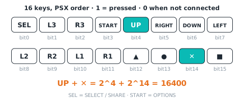
16 buttons buttons16
| Range | Meaning |
|---|---|
0~65535 bit |
all buttons in one 16-bit word (PSX layout): bit0 SELECT(SHARE), 1 L3, 2 R3, 3 START(OPTIONS), 4 up, 5 right, 6 down, 7 left, 8 L2, 9 R2, 10 L1, 11 R1, 12 triangle, 13 circle, 14 cross, 15 square; 1 = pressed; 0 when not connected |
int16_t buttons16 = mbcRead(0x42, 0x01); // 16 buttons:0~65535 bitThis value can itself be −32768 (top bit set, e.g. 0x8000), the same as MBC_NONE for no answer, so do not test for −32768: use mbcReadMany(0x42, 0x01, 1, &buttons16) instead; only a false return means no answer.
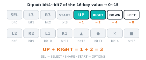
D-pad dpad
| Range | Meaning |
|---|---|
0~15 bit |
up 1, right 2, down 4, left 8, added when pressed together (0~15) |
int16_t dpad = mbcRead(0x42, 0x02); // D-pad:0~15 bitReturns MBC_NONE (−32768) when the module does not answer.
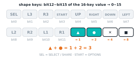
shape buttons shapeKeys
| Range | Meaning |
|---|---|
0~15 bit |
triangle 1, circle 2, cross 4, square 8, added when pressed together (0~15) |
int16_t shapeKeys = mbcRead(0x42, 0x03); // shape buttons:0~15 bitReturns MBC_NONE (−32768) when the module does not answer.
shoulder buttons shoulderKeys
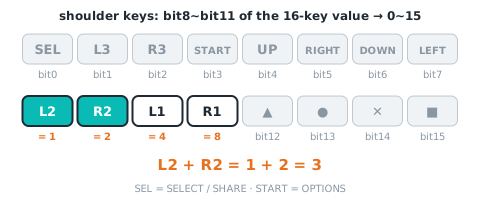
| Range | Meaning |
|---|---|
0~15 bit |
L2 1, R2 2, L1 4, R1 8, added when pressed together (0~15) |
int16_t shoulderKeys = mbcRead(0x42, 0x04); // shoulder buttons:0~15 bitReturns MBC_NONE (−32768) when the module does not answer.
function buttons funcKeys
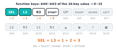
| Range | Meaning |
|---|---|
0~15 bit |
SELECT(SHARE) 1, L3 2, R3 4, START(OPTIONS) 8, added when pressed together (0~15) |
int16_t funcKeys = mbcRead(0x42, 0x05); // function buttons:0~15 bitReturns MBC_NONE (−32768) when the module does not answer.
connected connected
| Range | Meaning |
|---|---|
0~1 |
1 = gamepad connected and data seen within 300 ms, 0 = not connected (buttons 0, sticks centred while disconnected) |
int16_t connected = mbcRead(0x42, 0x06); // connected:0~1Returns MBC_NONE (−32768) when the module does not answer.
battery battery
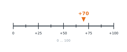
| Range | Meaning |
|---|---|
0~100 % |
gamepad battery 0~100 (always 0 on the PS2 receiver) |
int16_t battery = mbcRead(0x42, 0x07); // battery:0~100 %Returns MBC_NONE (−32768) when the module does not answer.
L2 analog l2Analog
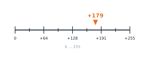
| Range | Meaning |
|---|---|
0~255 |
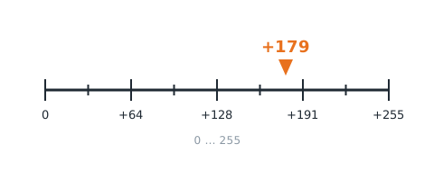
L2 trigger depth 0~255 (0 when not connected) |
int16_t l2Analog = mbcRead(0x42, 0x08); // L2 analog:0~255Returns MBC_NONE (−32768) when the module does not answer.
R2 analog r2Analog
| Range | Meaning |
|---|---|
0~255 |
R2 trigger depth 0~255 (0 when not connected) |
int16_t r2Analog = mbcRead(0x42, 0x09); // R2 analog:0~255Returns MBC_NONE (−32768) when the module does not answer.
system buttons sysKeys
| Range | Meaning |
|---|---|
0~3 bit |
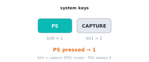
b0 PS button, b1 capture (PS5 mute) button; 0 when not connected (always 0 on PS2) |
int16_t sysKeys = mbcRead(0x42, 0x0A); // system buttons:0~3 bitReturns MBC_NONE (−32768) when the module does not answer.
gamepad type padType
| Range | Meaning |
|---|---|
0~4 |
0 none, 1 PS2 digital, 2 PS2 analog, 3 PS4, 4 PS5 (or other) |
int16_t padType = mbcRead(0x42, 0x0B); // gamepad type:0~4Returns MBC_NONE (−32768) when the module does not answer.
stick axis 1~4 stick
| Range | Meaning |
|---|---|
-100~+100 |
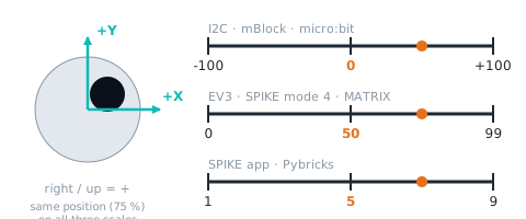
10 LX, 11 LY, 12 RX, 13 RY: −100 to +100, 0 = centre, right/up positive; 0 when not connected |
int16_t stick[4];
mbcReadMany(0x42, 0x10, 4, stick);   // stick axis 1~4:-100~+100
for (uint8_t i = 0; i < 4; i++) { Serial.print(stick[i]); Serial.print(' '); }
Serial.println();
Ids 0x10~0x13 are consecutive: one mbcReadMany call returns them from the same 10 ms snapshot.
Commands
rumble rumble
[strength 0~255], 0 = stop; 200 ms per call (ignored by PS2)
mbcWrite(0x42, 0xE5, 128); // rumble(strength 0~255)light bar colour lightbar
[R][G][B] each 0~255, exactly 3 bytes; remembered until connected; default blue (0,0,255) (ignored by PS2)
mbcWrite(0x42, 0xE6, 128, 128, 128); // light bar colour(R 0~255, G 0~255, B 0~255)Examples
This page has 8 examples, from "is it connected?" all the way to a "tank-style remote-control car", plus the rumble and light bar that only PS4/PS5 gamepads have. You can copy and upload each example as it is, and every line of the code has an English comment. Never written code before? No problem. Just do them one by one, in order.
Tip
First time using Arduino? Read 🔰 First Time with Arduino: Start from Zero first. In 15 minutes you learn how to install the software, upload a program and see the result.
Wiring (the same for every example)
| Receiver | Arduino UNO / Nano | Arduino UNO R4 | ESP32 |
|---|---|---|---|
| VCC | 5V | 5V | 5V (VIN) |
| GND | GND | GND | GND |
| RX (= SDA) | A4 | SDA | GPIO 21 |
| TX (= SCL) | A5 | SCL | GPIO 22 |
Important
- Use the Universal I2C edition of the receiver. The SPIKE and EV3 editions have different firmware and cannot connect to Arduino directly.
- The receiver is marked TX, RX: on the I2C edition TX is SCL and RX is SDA.
- The receiver has a built-in level shifter, so UNO (5 V), UNO R4 and ESP32 (3.3 V) can all connect directly.
- Unplug the USB cable before you connect the wires.
First time: pair the gamepad with the receiver
The gamepad must be "paired" first, so the receiver knows it. You only do this once; after that it connects automatically.
- Wire it up as above and plug the Arduino into USB (this powers the receiver).
- A brand-new receiver waits 30 seconds for a gamepad after power-on. If it is already paired and you want to change the gamepad, press the Reset button on the receiver; it waits 30 seconds the same way. When the green light on the receiver blinks fast, it is waiting for a gamepad.
- Within these 30 seconds, put the gamepad into pairing mode:
- PS4 gamepad: hold SHARE + PS at the same time until the light bar blinks fast.
- PS5 gamepad: hold Create + PS at the same time until the light bar blinks fast.
- Once connected, the receiver remembers this gamepad. From now on, just press the PS button on the gamepad and it connects automatically.
Tip
When many groups pair at the same time in a classroom, do it one group at a time. Otherwise another group's gamepad may also be in pairing mode during the 30 seconds and connect to the wrong receiver. If the wrong gamepad got paired, press Reset and pair again.
Command overview (what this receiver can give you)
Think of the receiver as a row of numbered "boxes". Each box holds one number (int16). Write [number], then read 2 bytes, and you get one value. Boxes next to each other can be read in one row (up to 16). In the examples, mbcRead(ADDR, number) and mbcReadMany(ADDR, first number, how many, array) do exactly this.
| Number | Name | Range / unit | Meaning | Used in |
|---|---|---|---|---|
01 |
16 buttons | 0~65535 (bits) | All 16 buttons in one number (PSX order): bit0 SELECT(SHARE), 1 L3, 2 R3, 3 START(OPTIONS), 4 ↑, 5 →, 6 ↓, 7 ←, 8 L2, 9 R2, 10 L1, 11 R1, 12 ▲, 13 ●, 14 ✕, 15 ■; 1 = pressed | Examples 2, 3, 7 |
02 |
D-pad | 0~15 | ↑ 1, → 2, ↓ 4, ← 8; pressing several adds them up | Examples 2, 3 |
03 |
Shape buttons | 0~15 | ▲ 1, ● 2, ✕ 4, ■ 8 | Examples 2, 3 |
04 |
Shoulder buttons | 0~15 | L2 1, R2 2, L1 4, R1 8 | Examples 2, 3 |
05 |
Function buttons | 0~15 | SELECT(SHARE) 1, L3 2, R3 4, START(OPTIONS) 8 | Examples 2, 3 |
06 |
Connected | 0~1 | 1 = gamepad connected and data received within the last 0.3 s; when disconnected all buttons are 0 and sticks are 0 | Examples 2, 5, 6 |
07 |
Battery | 0~100 % | Gamepad battery level | Examples 1, 2, 5 |
08 |
L2 analog | 0~255 | How hard L2 is pressed | Examples 2, 5 |
09 |
R2 analog | 0~255 | How hard R2 is pressed | Examples 2, 5, 7 |
0A |
System buttons | bits | b0 PS button, b1 capture button (PS5: mute button) | Examples 2, 5 |
0B |
Gamepad type | 0~4 | 0 none, 1 PS2 digital, 2 PS2 analog, 3 PS4, 4 PS5 (or other) | Examples 2, 5 |
10~`13` |
Sticks LX / LY / RX / RY | −100~+100 | 0 = middle, right / up are positive | Examples 2, 4, 6, 8 |
F0 |
Device ID | — | low byte = factory address 0x42, high byte = type (1 PS2, 2 PS4/PS5) | Example 1 |
F1 |
Protocol version | 2 | These examples are written for version 2 | Example 1 |
F2 |
Firmware version | major x 100 + minor | for example 102 = 1.2 | Example 1 |
F3 |
Status flags | bits | b0 ready, b1 gamepad connected | Example 1, mbcWaitReady in every example |
F5 |
Seconds since power-on | 0~32767 | If the number gets smaller, the receiver has restarted | Example 1 |
E5 (write) |
Rumble | [strength 0~255] | 0 = stop; each command rumbles for 200 ms | Example 7 |
E6 (write) |
Light bar color | [R][G][B] | each 0~255, must be exactly 3 bytes; remembered while not connected | Example 8 |
Note
A box that does not exist (for example
0C~`0F) reads as-32768(calledMBC_NONEin the examples). You also get-32768` when the receiver cannot be read. Full specification: MBC Universal I2C Protocol v2.
All Examples
| # | Example | What you learn | You also need |
|---|---|---|---|
| 1 | Say hello to the receiver | Check the wiring, read the ID card (F0~F3), see whether the gamepad is connected | Nothing |
| 2 | Print all the values at once | See what every box holds (01 |
Nothing |
| 3 | Which button did you press? | Split the 16-button value into bits, the four button groups | Nothing |
| 4 | How far is the stick pushed? | Sticks ±100, drawn as a cross chart | Nothing |
| 5 | Gamepad status | Connection, battery, analog triggers, PS button, gamepad type | Nothing |
| 6 | Tank-style remote-control car (advanced) | Drive with two sticks, stop automatically on disconnect | Two-wheel car, L298N motor driver board |
| 7 | Make the gamepad rumble | Write command E5 | Nothing |
| 8 | Set the light bar color with the sticks | Write command E6 (3 parameters) | Nothing |
Tip
Suggested order: 1 → 2 → 3 → 4 → 5 → 7 → 8 → 6. Only example 6 needs extra parts.
1️⃣ Say hello to the receiver
What it does: Checks that the receiver is connected and prints its "ID card" (factory address, type, protocol version, firmware version, status flags). Then it keeps watching the gamepad and tells you when it connects or disconnects. Run this one first every time you connect a new receiver.
Steps:
- Connect the 4 wires as in the table above, then plug the USB cable into the computer.
- Copy the code below, paste it into the Arduino IDE and click → Upload.
- Open the Serial Monitor (the magnifying glass at the top right) and choose 115200 baud.
- Press the PS button on the gamepad and watch for "Gamepad connected!". (A gamepad that has never been paired: follow the pairing steps above first.)
/*
 * Controller PS4/PS5 x Arduino   Example 1: Say hello to the receiver
 * ------------------------------------------------------------
 * What does this example do?
 *   Checks that the receiver is connected. If it is, it prints the receiver's
 *   "ID card" (device ID, type, protocol version, firmware version) and its
 *   current status. Then it keeps watching the gamepad: it tells you when the
 *   gamepad connects and when it disconnects.
 *   Run this example first every time you connect a new receiver.
 *
 * You need: Controller PS4/PS5 receiver (Universal I2C edition) + a PS4 or PS5 gamepad (already paired), Arduino UNO / Nano / UNO R4 or ESP32.
 *
 * Wiring:
 *   Receiver VCC -> 5V      Receiver GND -> GND
 *   Receiver RX (= SDA) -> A4      Receiver TX (= SCL) -> A5         (UNO / Nano)
 *   UNO R4: SDA / SCL pins; ESP32: GPIO 21 (SDA) / GPIO 22 (SCL)
 *   (On the I2C edition, the pin marked TX is SCL and RX is SDA)
 *
 * How to see the result:
 *   After uploading, open the Serial Monitor and choose 115200 baud.
 *   Press the PS button on the gamepad to connect it and watch for "Gamepad connected!".
 *
 * Tip:
 *   The first time, you must pair: within 30 s after the receiver powers on (or after you press Reset),
 *   hold SHARE + PS on a PS4 gamepad, or Create + PS on a PS5 gamepad, until the light bar blinks fast.
 */

#include <Wire.h>                        // Arduino's built-in I2C tool, used to talk to the receiver

const uint8_t ADDR = 0x42;               // The receiver's "house number" (I2C address). PS2 and PS4 are both 0x42
const int16_t MBC_NONE = -32768;         // Code for "no such value / could not read"

// Helper declaration (the code is at the bottom of the file); mbcWrite's parameters can be left out
bool mbcWrite(uint8_t addr, uint8_t id, const uint8_t *p = NULL, uint8_t n = 0);

bool wasConnected = false;               // Was the gamepad connected the last time we looked?

void setup() {
  Serial.begin(115200);                  // Open the channel to the computer at 115200 baud
  mbcBegin();                            // Get I2C ready (helper at the bottom of the file)
  delay(500);                            // Give the receiver 0.5 s to boot

  Serial.println(F("=== Controller PS4/PS5: Say hello to the receiver ==="));

  // Wait until the receiver says "I am ready" (bit0 of status flags F3), up to 5 seconds
  if (!mbcWaitReady(ADDR, 5000)) {
    Serial.println(F("Receiver not found! Please check:"));
    Serial.println(F("  1. RX (SDA) -> A4, TX (SCL) -> A5 (ESP32: 21 / 22). Are they swapped?"));
    Serial.println(F("  2. VCC -> 5V, GND -> GND. Plugged in firmly? Is the light on the receiver on?"));
    Serial.println(F("  3. Is your receiver the Universal I2C edition? (SPIKE and EV3 editions cannot connect to Arduino)"));
    while (true) {}                      // Stop here if not found
  }

  // ---- F0 device ID: low byte = factory address, high byte = type (1 = PS2, 2 = PS4/PS5) ----
  int16_t id = mbcRead(ADDR, 0xF0);
  uint8_t factoryAddr = (uint8_t)(id & 0xFF);        // Factory address (stays the same even if you changed the address)
  uint8_t kind        = (uint8_t)((id >> 8) & 0xFF); // hw[0]: 1 = PS2 receiver, 2 = PS4/PS5 receiver
  Serial.print(F("Found it! Factory address 0x"));
  Serial.println(factoryAddr, HEX);      // Should be 42
  Serial.print(F("Type: "));
  if (kind == 1)      Serial.println(F("PS2 2.4G receiver"));
  else if (kind == 2) Serial.println(F("PS4/PS5 Bluetooth receiver"));
  else                Serial.println(F("Unknown type"));

  // ---- F1 protocol version (these examples are written for version 2) ----
  Serial.print(F("Protocol version: "));
  Serial.println(mbcRead(ADDR, 0xF1));

  // ---- F2 firmware version: major x 100 + minor (for example 102 = 1.2) ----
  int16_t fw = mbcRead(ADDR, 0xF2);
  Serial.print(F("Firmware version: "));
  Serial.print(fw / 100);
  Serial.print('.');
  Serial.println(fw % 100);

  // ---- F3 status flags: each bit means one thing ----
  int16_t st = mbcRead(ADDR, 0xF3);
  Serial.println(F("Current status:"));
  Serial.print(F("  bit0 ready              ")); Serial.println((st & 0x01) ? F("yes") : F("no"));
  Serial.print(F("  bit1 gamepad connected  ")); Serial.println((st & 0x02) ? F("yes") : F("no"));

  // ---- F5 seconds since power-on (just to see how long it has been running) ----
  Serial.print(F("Seconds since power-on: "));
  Serial.println(mbcRead(ADDR, 0xF5));

  Serial.println(F("Wiring is correct! Now press the PS button on the gamepad to connect it."));
}

void loop() {
  // Every pass, look at bit1 of F3 (is the gamepad connected?). Only print when it changes, so the screen stays clean
  int16_t st = mbcRead(ADDR, 0xF3);
  if (st == MBC_NONE) {                  // Could not read = a wire came loose
    Serial.println(F("Cannot read the receiver. Did a wire come loose?"));
    delay(1000);
    return;
  }
  bool connected = st & 0x02;
  if (connected != wasConnected) {
    if (connected) {
      Serial.print(F("Gamepad connected! Battery "));
      Serial.print(mbcRead(ADDR, 0x07));  // 07 battery 0~100 (a PS2 gamepad has no battery level, always 0)
      Serial.println(F("%"));
    } else {
      Serial.println(F("Gamepad not connected"));
    }
    wasConnected = connected;
  }
  delay(50);
}

// ============================================================
// Below are the "Communication helpers" (MBC I2C protocol v2): they talk to the sensor.
// They are the same in every MBC example. No need to change or understand them.
//   How to read: write [number] -> wait 2 ms -> read 2 x k bytes = k int16 values (little-endian) starting at that number
//   If the number does not exist (empty slot), the sensor returns -32768 (MBC_NONE)
// ============================================================

// Start I2C (call once in setup)
// UNO/Nano: SDA=A4, SCL=A5; UNO R4: SDA/SCL pins; ESP32: default GPIO21(SDA)/22(SCL)
void mbcBegin() {
  Wire.begin();
#if defined(WIRE_HAS_TIMEOUT)
  Wire.setWireTimeout(25000, true);      // If a wire is loose, the Arduino will not freeze
#endif
}

// From the sensor at address addr, read k values (1~16) in a row starting at number id, into out. Returns true if all were read
bool mbcReadMany(uint8_t addr, uint8_t id, uint8_t k, int16_t *out) {
  if (k < 1) k = 1;
  if (k > 16) k = 16;                    // At most 16 values at a time (32 bytes, the Wire buffer limit)
  Wire.beginTransmission(addr);
  Wire.write(id);                        // Tell the sensor: I want to read starting at number id
  if (Wire.endTransmission() != 0) return false;
  delay(2);                              // Wait 2 ms before reading (ESP32-based products need this)
  uint8_t n = (uint8_t)(2 * k);
  if (Wire.requestFrom(addr, n) != n) return false;
  for (uint8_t i = 0; i < k; i++) {
    uint16_t lo = Wire.read();           // The low byte comes first
    uint16_t hi = Wire.read();           // Then the high byte (little-endian)
    out[i] = (int16_t)(uint16_t)(lo | (hi << 8));
  }
  return true;
}

// Read one value. Returns MBC_NONE if it cannot be read (not connected)
int16_t mbcRead(uint8_t addr, uint8_t id) {
  int16_t v;
  return mbcReadMany(addr, id, 1, &v) ? v : MBC_NONE;
}

// Send a command: write [id][parameters...]. p points to the parameters, n = how many bytes (leave out if none). Returns true on success
bool mbcWrite(uint8_t addr, uint8_t id, const uint8_t *p, uint8_t n) {
  Wire.beginTransmission(addr);
  Wire.write(id);
  for (uint8_t i = 0; i < n; i++) Wire.write(p[i]);
  return Wire.endTransmission() == 0;
}

// Wait until the sensor is ready (bit0 of status flags F3 = 1), up to ms milliseconds. Returns true when ready
bool mbcWaitReady(uint8_t addr, uint16_t ms) {
  unsigned long start = millis();
  while (millis() - start < ms) {
    int16_t f = mbcRead(addr, 0xF3);
    if (f != MBC_NONE && (f & 1)) return true;
    delay(50);
  }
  return false;
}
You will see: (gamepad connects, then you hold the PS button for 10 s to turn it off)
=== Controller PS4/PS5: Say hello to the receiver ===
Found it! Factory address 0x42
Type: PS4/PS5 Bluetooth receiver
Protocol version: 2
Firmware version: 1.2
Current status:
  bit0 ready              yes
  bit1 gamepad connected  no
Seconds since power-on: 3
Wiring is correct! Now press the PS button on the gamepad to connect it.
Gamepad connected! Battery 80%
Gamepad not connected
Note
What are the "Communication helpers"? At the bottom of every example there is the same piece of code. It "talks" to the receiver. You don't need to change it or understand it. Just remember:
mbcRead(ADDR, number): read one value (returns-32768if it cannot be read)mbcReadMany(ADDR, first number, how many, array): read a row of values starting at a number (up to 16, all from the same instant)mbcWrite(ADDR, command, parameters, how many bytes): send a command (for example rumble, light bar)mbcWaitReady(ADDR, milliseconds): wait until the receiver has bootedThe helpers contain one line
delay(2)(wait 2 ms after writing the number, before reading). Do not remove it: the PS4/PS5 receiver is built on an ESP32 and needs these 2 ms to prepare the data.
2️⃣ Print all the values at once
What it does: Every 0.5 s it prints every value in the value table: 010B in one read of 11, 1013 in one read of 4. Press buttons and push the sticks, watch which line changes, and you know what each box is.
Download ps4_02_all_values.ino
/*
 * Controller PS4/PS5 x Arduino   Example 2: Print all the values at once
 * ------------------------------------------------------------
 * What does this example do?
 *   Every 0.5 s it prints every value in the receiver's "value table", so you can
 *   see what each number holds:
 *     01~0B: buttons, connection, battery, triggers, system buttons, gamepad type (11 values in one read)
 *     10~13: the four stick axes LX, LY, RX, RY (4 values in one read)
 *   Numbers that are next to each other can be read "in one row" (mbcReadMany),
 *   and you get the values from the same instant.
 *
 * You need: Controller PS4/PS5 receiver (Universal I2C edition) + a PS4 or PS5 gamepad (already paired), Arduino UNO / Nano / UNO R4 or ESP32.
 *
 * Wiring:
 *   Receiver VCC -> 5V      Receiver GND -> GND
 *   Receiver RX (= SDA) -> A4      Receiver TX (= SCL) -> A5         (UNO / Nano)
 *   UNO R4: SDA / SCL pins; ESP32: GPIO 21 (SDA) / GPIO 22 (SCL)
 *   (On the I2C edition, the pin marked TX is SCL and RX is SDA)
 *
 * How to see the result:
 *   After uploading, open the Serial Monitor and choose 115200 baud. Press buttons, push the sticks, and watch which number changes.
 *
 * Tip:
 *   The first time, you must pair: within 30 s after the receiver powers on (or after you press Reset),
 *   hold SHARE + PS on a PS4 gamepad, or Create + PS on a PS5 gamepad, until the light bar blinks fast.
 */

#include <Wire.h>                        // Arduino's built-in I2C tool

const uint8_t ADDR = 0x42;               // The receiver's "house number" (I2C address). PS2 and PS4 are both 0x42
const int16_t MBC_NONE = -32768;         // Code for "no such value / could not read"

// Helper declaration (the code is at the bottom of the file); mbcWrite's parameters can be left out
bool mbcWrite(uint8_t addr, uint8_t id, const uint8_t *p = NULL, uint8_t n = 0);

unsigned long lastPrint = 0;             // When we last printed

void setup() {
  Serial.begin(115200);
  mbcBegin();
  delay(500);
  if (!mbcWaitReady(ADDR, 5000)) {
    Serial.println(F("Receiver not found. Run Example 1 first to check the wiring."));
    while (true) {}
  }
  Serial.println(F("Ready! Printing all values every 0.5 s."));
}

void loop() {
  if (millis() - lastPrint >= 500) {     // 👉 You can change this: print every 0.5 s
    lastPrint = millis();

    // ---- Part 1: numbers 01~0B, 11 values in one read ----
    int16_t a[11];
    if (!mbcReadMany(ADDR, 0x01, 11, a)) { Serial.println(F("Cannot read (part 1)")); return; }
    // ---- Part 2: numbers 10~13, 4 values in one read ----
    int16_t s[4];
    if (!mbcReadMany(ADDR, 0x10, 4, s)) { Serial.println(F("Cannot read (part 2)")); return; }

    Serial.println(F("------------------------------"));
    Serial.print(F("01 16 buttons (PSX order, binary): ")); printBits16((uint16_t)a[0]); Serial.println();
    Serial.print(F("02 D-pad (up1 right2 down4 left8)     : ")); Serial.println(a[1]);
    Serial.print(F("03 Shape buttons (▲1 ●2 ✕4 ■8)        : ")); Serial.println(a[2]);
    Serial.print(F("04 Shoulder (L2 1 R2 2 L1 4 R1 8)      : ")); Serial.println(a[3]);
    Serial.print(F("05 Function (SELECT1 L3 2 R3 4 START8) : ")); Serial.println(a[4]);
    Serial.print(F("06 Connected (1 = yes)                 : ")); Serial.println(a[5]);
    Serial.print(F("07 Battery 0~100        : ")); Serial.println(a[6]);
    Serial.print(F("08 L2 analog 0~255                     : ")); Serial.println(a[7]);
    Serial.print(F("09 R2 analog 0~255                     : ")); Serial.println(a[8]);
    Serial.print(F("0A System buttons (b0 PS, b1 capture)  : ")); Serial.println(a[9]);
    Serial.print(F("0B Gamepad type 0~4                    : ")); Serial.println(a[10]);
    Serial.print(F("10 LX  11 LY  12 RX  13 RY (±100): "));
    for (uint8_t i = 0; i < 4; i++) { Serial.print(s[i]); Serial.print(i < 3 ? F("  ") : F("")); }
    Serial.println();
  }
  delay(50);
}

// Print a 16-bit number as 16 zeros and ones (left = bit15 ■, right = bit0 SELECT)
void printBits16(uint16_t v) {
  for (int8_t i = 15; i >= 0; i--) {
    Serial.print((v >> i) & 1);
    if (i % 4 == 0 && i > 0) Serial.print(' ');   // A space every 4 bits, easier to read
  }
}

// ============================================================
// Below are the "Communication helpers" (MBC I2C protocol v2): they talk to the sensor.
// They are the same in every MBC example. No need to change or understand them.
//   How to read: write [number] -> wait 2 ms -> read 2 x k bytes = k int16 values (little-endian) starting at that number
//   If the number does not exist (empty slot), the sensor returns -32768 (MBC_NONE)
// ============================================================

// Start I2C (call once in setup)
// UNO/Nano: SDA=A4, SCL=A5; UNO R4: SDA/SCL pins; ESP32: default GPIO21(SDA)/22(SCL)
void mbcBegin() {
  Wire.begin();
#if defined(WIRE_HAS_TIMEOUT)
  Wire.setWireTimeout(25000, true);      // If a wire is loose, the Arduino will not freeze
#endif
}

// From the sensor at address addr, read k values (1~16) in a row starting at number id, into out. Returns true if all were read
bool mbcReadMany(uint8_t addr, uint8_t id, uint8_t k, int16_t *out) {
  if (k < 1) k = 1;
  if (k > 16) k = 16;                    // At most 16 values at a time (32 bytes, the Wire buffer limit)
  Wire.beginTransmission(addr);
  Wire.write(id);                        // Tell the sensor: I want to read starting at number id
  if (Wire.endTransmission() != 0) return false;
  delay(2);                              // Wait 2 ms before reading (ESP32-based products need this)
  uint8_t n = (uint8_t)(2 * k);
  if (Wire.requestFrom(addr, n) != n) return false;
  for (uint8_t i = 0; i < k; i++) {
    uint16_t lo = Wire.read();           // The low byte comes first
    uint16_t hi = Wire.read();           // Then the high byte (little-endian)
    out[i] = (int16_t)(uint16_t)(lo | (hi << 8));
  }
  return true;
}

// Read one value. Returns MBC_NONE if it cannot be read (not connected)
int16_t mbcRead(uint8_t addr, uint8_t id) {
  int16_t v;
  return mbcReadMany(addr, id, 1, &v) ? v : MBC_NONE;
}

// Send a command: write [id][parameters...]. p points to the parameters, n = how many bytes (leave out if none). Returns true on success
bool mbcWrite(uint8_t addr, uint8_t id, const uint8_t *p, uint8_t n) {
  Wire.beginTransmission(addr);
  Wire.write(id);
  for (uint8_t i = 0; i < n; i++) Wire.write(p[i]);
  return Wire.endTransmission() == 0;
}

// Wait until the sensor is ready (bit0 of status flags F3 = 1), up to ms milliseconds. Returns true when ready
bool mbcWaitReady(uint8_t addr, uint16_t ms) {
  unsigned long start = millis();
  while (millis() - start < ms) {
    int16_t f = mbcRead(addr, 0xF3);
    if (f != MBC_NONE && (f & 1)) return true;
    delay(50);
  }
  return false;
}
You will see: (holding ✕ and ↑, left stick pushed all the way right)
Ready! Printing all values every 0.5 s.
------------------------------
01 16 buttons (PSX order, binary): 0100 0000 0001 0000
02 D-pad (up1 right2 down4 left8)     : 1
03 Shape buttons (▲1 ●2 ✕4 ■8)        : 4
04 Shoulder (L2 1 R2 2 L1 4 R1 8)      : 0
05 Function (SELECT1 L3 2 R3 4 START8) : 0
06 Connected (1 = yes)                 : 1
07 Battery 0~100 (PS2 always 0)        : 80
08 L2 analog 0~255                     : 0
09 R2 analog 0~255                     : 0
0A System buttons (b0 PS, b1 capture)  : 0
0B Gamepad type 0~4                    : 3
10 LX  11 LY  12 RX  13 RY (±100): 100  0  0  0
Tip
In the binary line, the left end is bit15 (■) and the right end is bit0 (SELECT). Above, ✕ is bit14 and ↑ is bit4, so you see two 1s.
3️⃣ Which button did you press?
What it does: Press any button on the gamepad and the computer tells you which one; it also tells you when you release it. You can press several at the same time. When any of the four "button groups" (D-pad, shape, shoulder, function) changes, it prints one more line.
/*
 * Controller PS4/PS5 x Arduino   Example 3: Which button did you press?
 * ------------------------------------------------------------
 * What does this example do?
 *   Press any button on the gamepad and the computer tells you which one. It also
 *   tells you when you release it. You can press several buttons at the same time.
 *   The state of all 16 buttons is packed into one number (number 01, "16 buttons").
 *   Each button takes one "bit": pressed = 1, not pressed = 0, like 16 light switches in a row.
 *   Numbers 02~05 are the same buttons in "groups": D-pad, shape buttons, shoulder
 *   buttons, function buttons, 4 buttons each. Each group is 0~15; pressing several
 *   adds them up (for example up + right = 1 + 2 = 3).
 *
 * You need: Controller PS4/PS5 receiver (Universal I2C edition) + a PS4 or PS5 gamepad (already paired), Arduino UNO / Nano / UNO R4 or ESP32.
 *
 * Wiring:
 *   Receiver VCC -> 5V      Receiver GND -> GND
 *   Receiver RX (= SDA) -> A4      Receiver TX (= SCL) -> A5         (UNO / Nano)
 *   UNO R4: SDA / SCL pins; ESP32: GPIO 21 (SDA) / GPIO 22 (SCL)
 *   (On the I2C edition, the pin marked TX is SCL and RX is SDA)
 *
 * How to see the result:
 *   After uploading, open the Serial Monitor and choose 115200 baud. Press the PS button on the gamepad to connect it, then press buttons.
 *
 * Tip:
 *   The first time, you must pair: within 30 s after the receiver powers on (or after you press Reset),
 *   hold SHARE + PS on a PS4 gamepad, or Create + PS on a PS5 gamepad, until the light bar blinks fast.
 *   The PS button and the capture button are not in the 16 buttons; they are in number 0A system buttons (b0 PS, b1 capture).
 */

#include <Wire.h>                        // Arduino's built-in I2C tool

const uint8_t ADDR = 0x42;               // The receiver's "house number" (I2C address). PS2 and PS4 are both 0x42
const int16_t MBC_NONE = -32768;         // Code for "no such value / could not read"

// Helper declaration (the code is at the bottom of the file); mbcWrite's parameters can be left out
bool mbcWrite(uint8_t addr, uint8_t id, const uint8_t *p = NULL, uint8_t n = 0);

uint16_t lastButtons = 0;                // The 16-button state we saw last time
int16_t  lastGroup[4] = {0, 0, 0, 0};    // The four groups 02~05 we saw last time

void setup() {
  Serial.begin(115200);
  mbcBegin();
  delay(500);
  if (!mbcWaitReady(ADDR, 5000)) {
    Serial.println(F("Receiver not found. Run Example 1 first to check the wiring."));
    while (true) {}
  }
  Serial.println(F("Ready! Press the buttons on the gamepad."));
}

void loop() {
  // Read numbers 01~05 (5 values) in one go: [0] 16 buttons [1] D-pad [2] shape [3] shoulder [4] function
  int16_t v[5];
  if (!mbcReadMany(ADDR, 0x01, 5, v)) {
    delay(100);                          // Could not read this time, try again shortly
    return;
  }
  uint16_t buttons = (uint16_t)v[0];     // 16 buttons: PSX order (bit0 SELECT ... bit15 ■)

  // ---- 1. Check button by button: which were "just pressed" and which were "just released" ----
  for (uint8_t i = 0; i < 16; i++) {
    uint16_t mask = 1u << i;             // The "bit" of button i
    bool now    = buttons & mask;        // Is it pressed now?
    bool before = lastButtons & mask;    // Was it pressed last time?
    if (now && !before) { Serial.print(F("Pressed: ")); printButtonName(i); Serial.println(); }
    if (!now && before) { Serial.print(F("Released: ")); printButtonName(i); Serial.println(); }
  }
  lastButtons = buttons;                 // Remember this state so we can compare next time

  // ---- 2. If any of the four group values changed, print one line (D-pad / shape / shoulder / function, each 0~15) ----
  bool changed = false;
  for (uint8_t i = 0; i < 4; i++) if (v[i + 1] != lastGroup[i]) changed = true;
  if (changed) {
    Serial.print(F("    Groups -> D-pad ")); Serial.print(v[1]);
    Serial.print(F("  Shape ")); Serial.print(v[2]);
    Serial.print(F("  Shoulder ")); Serial.print(v[3]);
    Serial.print(F("  Function ")); Serial.println(v[4]);
    for (uint8_t i = 0; i < 4; i++) lastGroup[i] = v[i + 1];
  }

  delay(50);                             // Check every 0.05 s, so even fast presses are caught
}

// Print the name of bit i in the 16-button value (PSX order)
void printButtonName(uint8_t i) {
  switch (i) {
    case 0:  Serial.print(F("SELECT (PS4: SHARE / PS5: Create)")); break;
    case 1:  Serial.print(F("L3 (press the left stick down)")); break;
    case 2:  Serial.print(F("R3 (press the right stick down)")); break;
    case 3:  Serial.print(F("START (PS4/PS5: OPTIONS)")); break;
    case 4:  Serial.print(F("↑ D-pad up")); break;
    case 5:  Serial.print(F("→ D-pad right")); break;
    case 6:  Serial.print(F("↓ D-pad down")); break;
    case 7:  Serial.print(F("← D-pad left")); break;
    case 8:  Serial.print(F("L2")); break;
    case 9:  Serial.print(F("R2")); break;
    case 10: Serial.print(F("L1")); break;
    case 11: Serial.print(F("R1")); break;
    case 12: Serial.print(F("▲ Triangle")); break;
    case 13: Serial.print(F("● Circle")); break;
    case 14: Serial.print(F("✕ Cross")); break;
    case 15: Serial.print(F("■ Square")); break;
  }
}

// ============================================================
// Below are the "Communication helpers" (MBC I2C protocol v2): they talk to the sensor.
// They are the same in every MBC example. No need to change or understand them.
//   How to read: write [number] -> wait 2 ms -> read 2 x k bytes = k int16 values (little-endian) starting at that number
//   If the number does not exist (empty slot), the sensor returns -32768 (MBC_NONE)
// ============================================================

// Start I2C (call once in setup)
// UNO/Nano: SDA=A4, SCL=A5; UNO R4: SDA/SCL pins; ESP32: default GPIO21(SDA)/22(SCL)
void mbcBegin() {
  Wire.begin();
#if defined(WIRE_HAS_TIMEOUT)
  Wire.setWireTimeout(25000, true);      // If a wire is loose, the Arduino will not freeze
#endif
}

// From the sensor at address addr, read k values (1~16) in a row starting at number id, into out. Returns true if all were read
bool mbcReadMany(uint8_t addr, uint8_t id, uint8_t k, int16_t *out) {
  if (k < 1) k = 1;
  if (k > 16) k = 16;                    // At most 16 values at a time (32 bytes, the Wire buffer limit)
  Wire.beginTransmission(addr);
  Wire.write(id);                        // Tell the sensor: I want to read starting at number id
  if (Wire.endTransmission() != 0) return false;
  delay(2);                              // Wait 2 ms before reading (ESP32-based products need this)
  uint8_t n = (uint8_t)(2 * k);
  if (Wire.requestFrom(addr, n) != n) return false;
  for (uint8_t i = 0; i < k; i++) {
    uint16_t lo = Wire.read();           // The low byte comes first
    uint16_t hi = Wire.read();           // Then the high byte (little-endian)
    out[i] = (int16_t)(uint16_t)(lo | (hi << 8));
  }
  return true;
}

// Read one value. Returns MBC_NONE if it cannot be read (not connected)
int16_t mbcRead(uint8_t addr, uint8_t id) {
  int16_t v;
  return mbcReadMany(addr, id, 1, &v) ? v : MBC_NONE;
}

// Send a command: write [id][parameters...]. p points to the parameters, n = how many bytes (leave out if none). Returns true on success
bool mbcWrite(uint8_t addr, uint8_t id, const uint8_t *p, uint8_t n) {
  Wire.beginTransmission(addr);
  Wire.write(id);
  for (uint8_t i = 0; i < n; i++) Wire.write(p[i]);
  return Wire.endTransmission() == 0;
}

// Wait until the sensor is ready (bit0 of status flags F3 = 1), up to ms milliseconds. Returns true when ready
bool mbcWaitReady(uint8_t addr, uint16_t ms) {
  unsigned long start = millis();
  while (millis() - start < ms) {
    int16_t f = mbcRead(addr, 0xF3);
    if (f != MBC_NONE && (f & 1)) return true;
    delay(50);
  }
  return false;
}
You will see: (press ✕, then press ↑ and R1 together)
Ready! Press the buttons on the gamepad.
Pressed: ✕ Cross
    Groups -> D-pad 0  Shape 4  Shoulder 0  Function 0
Released: ✕ Cross
    Groups -> D-pad 0  Shape 0  Shoulder 0  Function 0
Pressed: ↑ D-pad up
Pressed: R1
    Groups -> D-pad 1  Shape 0  Shoulder 8  Function 0
Which bit is each of the 16 buttons?
| Bit | Button | Bit | Button |
|---|---|---|---|
| 0 | SELECT (PS4: SHARE / PS5: Create) | 8 | L2 |
| 1 | L3 (press the left stick down) | 9 | R2 |
| 2 | R3 (press the right stick down) | 10 | L1 |
| 3 | START (PS4/PS5: OPTIONS) | 11 | R1 |
| 4 | ↑ up | 12 | ▲ Triangle |
| 5 | → right | 13 | ● Circle |
| 6 | ↓ down | 14 | ✕ Cross |
| 7 | ← left | 15 | ■ Square |
The PS button and the capture button are not in these 16 bits. They are in box 0A system buttons (b0 PS, b1 capture), which example 5 reads.
Tip
Try it: To know "is ✕ pressed?", just write
if (buttons & (1u << 14)) { ... }; or read box03(shape buttons) and writeif (v & 4).
4️⃣ How far is the stick pushed?
What it does: Turns the position of the two sticks into numbers (box 10 LX, 11 LY, 12 RX, 13 RY): released = 0, pushed right or up is positive, pushed left or down is negative, all the way is +100 or -100. Prints every 0.3 s and also draws two cross charts.
/*
 * Controller PS4/PS5 x Arduino   Example 4: How far is the stick pushed?
 * ------------------------------------------------------------
 * What does this example do?
 *   Turns the position of the two sticks into numbers (number 10 LX, 11 LY, 12 RX, 13 RY):
 *     released (in the middle) = 0; pushed right or up = positive, all the way = +100;
 *     pushed left or down = negative, all the way = -100.
 *   Prints the numbers every 0.3 s and draws two "cross charts": O is where the stick is now.
 *
 * You need: Controller PS4/PS5 receiver (Universal I2C edition) + a PS4 or PS5 gamepad (already paired), Arduino UNO / Nano / UNO R4 or ESP32.
 *
 * Wiring:
 *   Receiver VCC -> 5V      Receiver GND -> GND
 *   Receiver RX (= SDA) -> A4      Receiver TX (= SCL) -> A5         (UNO / Nano)
 *   UNO R4: SDA / SCL pins; ESP32: GPIO 21 (SDA) / GPIO 22 (SCL)
 *   (On the I2C edition, the pin marked TX is SCL and RX is SDA)
 *
 * How to see the result:
 *   After uploading, open the Serial Monitor and choose 115200 baud. Push the stick slowly and watch the O move.
 *
 * Tip:
 *   When the stick wobbles a little near the middle, the number stays at 0. The receiver does this on purpose
 *   (it is called a "dead zone"), so a car does not creep when you let go of the stick.
 *   The first time, you must pair: within 30 s after the receiver powers on (or after you press Reset),
 *   hold SHARE + PS on a PS4 gamepad, or Create + PS on a PS5 gamepad, until the light bar blinks fast.
 */

#include <Wire.h>                        // Arduino's built-in I2C tool

const uint8_t ADDR = 0x42;               // The receiver's "house number" (I2C address). PS2 and PS4 are both 0x42
const int16_t MBC_NONE = -32768;         // Code for "no such value / could not read"

// Helper declaration (the code is at the bottom of the file); mbcWrite's parameters can be left out
bool mbcWrite(uint8_t addr, uint8_t id, const uint8_t *p = NULL, uint8_t n = 0);

unsigned long lastPrint = 0;

void setup() {
  Serial.begin(115200);
  mbcBegin();
  delay(500);
  if (!mbcWaitReady(ADDR, 5000)) {
    Serial.println(F("Receiver not found. Run Example 1 first to check the wiring."));
    while (true) {}
  }
  Serial.println(F("Ready! Push the sticks."));
}

void loop() {
  if (millis() - lastPrint >= 300) {     // 👉 You can change this: print every 0.3 s
    lastPrint = millis();

    // Read numbers 10~13 (4 values) in one go: [0] LX [1] LY [2] RX [3] RY (-100 ~ +100)
    int16_t s[4];
    if (!mbcReadMany(ADDR, 0x10, 4, s)) { Serial.println(F("Cannot read the receiver")); return; }

    Serial.print(F("Left stick X ")); Serial.print(s[0]);
    Serial.print(F("  Y ")); Serial.print(s[1]);
    Serial.print(F("   |   Right stick X ")); Serial.print(s[2]);
    Serial.print(F("  Y ")); Serial.println(s[3]);
    drawCross(s[0], s[1], s[2], s[3]);   // Draw the two cross charts
  }
  delay(50);
}

// Draw two 7x7 cross charts (left stick and right stick side by side). The center is +, the stick position is O
//   X: -100 ~ +100 -> column 0 ~ 6 (left -> right); Y: up is positive, so +100 is the top row
void drawCross(int lx, int ly, int rx, int ry) {
  int lcol = map(lx, -100, 100, 0, 6), lrow = map(ly, 100, -100, 0, 6);
  int rcol = map(rx, -100, 100, 0, 6), rrow = map(ry, 100, -100, 0, 6);
  for (int row = 0; row < 7; row++) {
    for (int col = 0; col < 7; col++) Serial.print(cell(row, col, lrow, lcol));
    Serial.print(F("     "));            // 5 spaces between the two charts
    for (int col = 0; col < 7; col++) Serial.print(cell(row, col, rrow, rcol));
    Serial.println();
  }
  Serial.println();
}

// Decide which character to print in one cell: O = stick position, + = center, | and - = cross lines, . = empty
char cell(int row, int col, int posRow, int posCol) {
  if (row == posRow && col == posCol) return 'O';
  if (row == 3 && col == 3) return '+';
  if (col == 3) return '|';
  if (row == 3) return '-';
  return '.';
}

// ============================================================
// Below are the "Communication helpers" (MBC I2C protocol v2): they talk to the sensor.
// They are the same in every MBC example. No need to change or understand them.
//   How to read: write [number] -> wait 2 ms -> read 2 x k bytes = k int16 values (little-endian) starting at that number
//   If the number does not exist (empty slot), the sensor returns -32768 (MBC_NONE)
// ============================================================

// Start I2C (call once in setup)
// UNO/Nano: SDA=A4, SCL=A5; UNO R4: SDA/SCL pins; ESP32: default GPIO21(SDA)/22(SCL)
void mbcBegin() {
  Wire.begin();
#if defined(WIRE_HAS_TIMEOUT)
  Wire.setWireTimeout(25000, true);      // If a wire is loose, the Arduino will not freeze
#endif
}

// From the sensor at address addr, read k values (1~16) in a row starting at number id, into out. Returns true if all were read
bool mbcReadMany(uint8_t addr, uint8_t id, uint8_t k, int16_t *out) {
  if (k < 1) k = 1;
  if (k > 16) k = 16;                    // At most 16 values at a time (32 bytes, the Wire buffer limit)
  Wire.beginTransmission(addr);
  Wire.write(id);                        // Tell the sensor: I want to read starting at number id
  if (Wire.endTransmission() != 0) return false;
  delay(2);                              // Wait 2 ms before reading (ESP32-based products need this)
  uint8_t n = (uint8_t)(2 * k);
  if (Wire.requestFrom(addr, n) != n) return false;
  for (uint8_t i = 0; i < k; i++) {
    uint16_t lo = Wire.read();           // The low byte comes first
    uint16_t hi = Wire.read();           // Then the high byte (little-endian)
    out[i] = (int16_t)(uint16_t)(lo | (hi << 8));
  }
  return true;
}

// Read one value. Returns MBC_NONE if it cannot be read (not connected)
int16_t mbcRead(uint8_t addr, uint8_t id) {
  int16_t v;
  return mbcReadMany(addr, id, 1, &v) ? v : MBC_NONE;
}

// Send a command: write [id][parameters...]. p points to the parameters, n = how many bytes (leave out if none). Returns true on success
bool mbcWrite(uint8_t addr, uint8_t id, const uint8_t *p, uint8_t n) {
  Wire.beginTransmission(addr);
  Wire.write(id);
  for (uint8_t i = 0; i < n; i++) Wire.write(p[i]);
  return Wire.endTransmission() == 0;
}

// Wait until the sensor is ready (bit0 of status flags F3 = 1), up to ms milliseconds. Returns true when ready
bool mbcWaitReady(uint8_t addr, uint16_t ms) {
  unsigned long start = millis();
  while (millis() - start < ms) {
    int16_t f = mbcRead(addr, 0xF3);
    if (f != MBC_NONE && (f & 1)) return true;
    delay(50);
  }
  return false;
}
You will see: (left stick pushed to the top right corner, right stick released)
Ready! Push the sticks.
Left stick X 100  Y 100   |   Right stick X 0  Y 0
...|..O     ...|...
...|...     ...|...
...|...     ...|...
---+---     ---O---
...|...     ...|...
...|...     ...|...
...|...     ...|...
Note
When the stick wobbles a little near the middle, the number stays at
0. The receiver does this on purpose (it is called a "dead zone"), so a car does not creep when you let go of the stick.
5️⃣ Gamepad status
What it does: Every 0.5 s it prints boxes 06~`0B` (6 values in one read): connected, battery, how hard L2 / R2 are pressed, PS button / capture button, gamepad type. When the connection state changes, it prints an extra line.
/*
 * Controller PS4/PS5 x Arduino   Example 5: Gamepad status
 * ------------------------------------------------------------
 * What does this example do?
 *   Every 0.5 s it prints the status values that are not buttons or sticks (numbers 06~0B, 6 values in one read):
 *     06 connected (1 = yes), 07 battery 0~100, 08 how hard L2 is pressed 0~255,
 *     09 how hard R2 is pressed 0~255, 0A system buttons (b0 PS button, b1 capture button), 0B gamepad type.
 *   When the connection state changes, it prints an extra line to tell you.
 *
 * You need: Controller PS4/PS5 receiver (Universal I2C edition) + a PS4 or PS5 gamepad (already paired), Arduino UNO / Nano / UNO R4 or ESP32.
 *
 * Wiring:
 *   Receiver VCC -> 5V      Receiver GND -> GND
 *   Receiver RX (= SDA) -> A4      Receiver TX (= SCL) -> A5         (UNO / Nano)
 *   UNO R4: SDA / SCL pins; ESP32: GPIO 21 (SDA) / GPIO 22 (SCL)
 *   (On the I2C edition, the pin marked TX is SCL and RX is SDA)
 *
 * How to see the result:
 *   After uploading, open the Serial Monitor and choose 115200 baud. Press L2 and R2 slowly and watch the numbers; turn the gamepad off and watch "Connected" become 0.
 *
 * Tip:
 *   When you press L2 / R2, 08 / 09 go slowly from 0 to 255, so you can see a light press and a hard press.
 */

#include <Wire.h>                        // Arduino's built-in I2C tool

const uint8_t ADDR = 0x42;               // The receiver's "house number" (I2C address). PS2 and PS4 are both 0x42
const int16_t MBC_NONE = -32768;         // Code for "no such value / could not read"

// Helper declaration (the code is at the bottom of the file); mbcWrite's parameters can be left out
bool mbcWrite(uint8_t addr, uint8_t id, const uint8_t *p = NULL, uint8_t n = 0);

unsigned long lastPrint = 0;
int16_t lastConnected = -1;              // The connection state last time (-1 = not seen yet)

void setup() {
  Serial.begin(115200);
  mbcBegin();
  delay(500);
  if (!mbcWaitReady(ADDR, 5000)) {
    Serial.println(F("Receiver not found. Run Example 1 first to check the wiring."));
    while (true) {}
  }
  Serial.println(F("Ready! Printing the gamepad status every 0.5 s."));
}

void loop() {
  if (millis() - lastPrint >= 500) {     // 👉 You can change this: print every 0.5 s
    lastPrint = millis();

    // Read numbers 06~0B (6 values) in one go: [0] connected [1] battery [2] L2 [3] R2 [4] system buttons [5] gamepad type
    int16_t v[6];
    if (!mbcReadMany(ADDR, 0x06, 6, v)) { Serial.println(F("Cannot read the receiver")); return; }

    // If the connection state changed, print one line to tell you
    if (v[0] != lastConnected) {
      Serial.println(v[0] ? F(">>> Gamepad connected!") : F(">>> Gamepad not connected"));
      lastConnected = v[0];
    }

    Serial.print(F("Connected ")); Serial.print(v[0]);
    Serial.print(F(" | Battery ")); Serial.print(v[1]); Serial.print(F("%"));
    Serial.print(F(" | L2 ")); Serial.print(v[2]);
    Serial.print(F(" R2 ")); Serial.print(v[3]);
    Serial.print(F(" | PS button ")); Serial.print((v[4] & 0x01) ? 1 : 0);     // System buttons bit0
    Serial.print(F(" Capture ")); Serial.print((v[4] & 0x02) ? 1 : 0);     // System buttons bit1
    Serial.print(F(" | Gamepad: "));
    printPadType(v[5]);
    Serial.println();
  }
  delay(50);
}

// 0B gamepad type: 0 none, 1 PS2 digital, 2 PS2 analog, 3 PS4, 4 PS5 (or other)
void printPadType(int16_t t) {
  switch (t) {
    case 0: Serial.print(F("No gamepad")); break;
    case 1: Serial.print(F("PS2 gamepad (digital mode)")); break;
    case 2: Serial.print(F("PS2 gamepad (analog mode)")); break;
    case 3: Serial.print(F("PS4 gamepad")); break;
    case 4: Serial.print(F("PS5 gamepad (or other Bluetooth gamepad)")); break;
    default: Serial.print(F("Unknown"));
  }
}

// ============================================================
// Below are the "Communication helpers" (MBC I2C protocol v2): they talk to the sensor.
// They are the same in every MBC example. No need to change or understand them.
//   How to read: write [number] -> wait 2 ms -> read 2 x k bytes = k int16 values (little-endian) starting at that number
//   If the number does not exist (empty slot), the sensor returns -32768 (MBC_NONE)
// ============================================================

// Start I2C (call once in setup)
// UNO/Nano: SDA=A4, SCL=A5; UNO R4: SDA/SCL pins; ESP32: default GPIO21(SDA)/22(SCL)
void mbcBegin() {
  Wire.begin();
#if defined(WIRE_HAS_TIMEOUT)
  Wire.setWireTimeout(25000, true);      // If a wire is loose, the Arduino will not freeze
#endif
}

// From the sensor at address addr, read k values (1~16) in a row starting at number id, into out. Returns true if all were read
bool mbcReadMany(uint8_t addr, uint8_t id, uint8_t k, int16_t *out) {
  if (k < 1) k = 1;
  if (k > 16) k = 16;                    // At most 16 values at a time (32 bytes, the Wire buffer limit)
  Wire.beginTransmission(addr);
  Wire.write(id);                        // Tell the sensor: I want to read starting at number id
  if (Wire.endTransmission() != 0) return false;
  delay(2);                              // Wait 2 ms before reading (ESP32-based products need this)
  uint8_t n = (uint8_t)(2 * k);
  if (Wire.requestFrom(addr, n) != n) return false;
  for (uint8_t i = 0; i < k; i++) {
    uint16_t lo = Wire.read();           // The low byte comes first
    uint16_t hi = Wire.read();           // Then the high byte (little-endian)
    out[i] = (int16_t)(uint16_t)(lo | (hi << 8));
  }
  return true;
}

// Read one value. Returns MBC_NONE if it cannot be read (not connected)
int16_t mbcRead(uint8_t addr, uint8_t id) {
  int16_t v;
  return mbcReadMany(addr, id, 1, &v) ? v : MBC_NONE;
}

// Send a command: write [id][parameters...]. p points to the parameters, n = how many bytes (leave out if none). Returns true on success
bool mbcWrite(uint8_t addr, uint8_t id, const uint8_t *p, uint8_t n) {
  Wire.beginTransmission(addr);
  Wire.write(id);
  for (uint8_t i = 0; i < n; i++) Wire.write(p[i]);
  return Wire.endTransmission() == 0;
}

// Wait until the sensor is ready (bit0 of status flags F3 = 1), up to ms milliseconds. Returns true when ready
bool mbcWaitReady(uint8_t addr, uint16_t ms) {
  unsigned long start = millis();
  while (millis() - start < ms) {
    int16_t f = mbcRead(addr, 0xF3);
    if (f != MBC_NONE && (f & 1)) return true;
    delay(50);
  }
  return false;
}
You will see: (gamepad connected, L2 pressed halfway, holding the PS button)
Ready! Printing the gamepad status every 0.5 s.
>>> Gamepad connected!
Connected 1 | Battery 80% | L2 0 R2 0 | PS button 0 Capture 0 | Gamepad: PS4 gamepad
Connected 1 | Battery 80% | L2 128 R2 0 | PS button 1 Capture 0 | Gamepad: PS4 gamepad
6️⃣ Tank-style remote-control car (advanced)
What it does: Drives a two-wheel car with the two sticks: left stick up/down (LY) controls the left wheel, right stick up/down (RY) controls the right wheel. The stick value -100~`+100` is multiplied straight into the speed. If the gamepad disconnects or the receiver cannot be read, the car stops at once.
You also need: A two-wheel car, an L298N motor driver board (or a TB6612 wired the same way), and batteries.
Motor wiring:
| L298N | Arduino UNO / Nano / R4 | ESP32 |
|---|---|---|
| ENA, IN1, IN2 (left wheel) | 5, 7, 8 | 25, 26, 27 |
| ENB, IN3, IN4 (right wheel) | 6, 9, 10 | 14, 32, 33 |
| GND | GND | GND |
Warning
Before the first run, lift the car up (wheels in the air) and upload: push both sticks up and check that both wheels turn forward (if one turns the wrong way, change
LEFT_REVERSE/RIGHT_REVERSE). Then turn the gamepad off and check that the wheels stop. Only then put the car on the floor.
/*
 * Controller PS4/PS5 x Arduino   Example 6: Tank-style remote-control car (advanced)
 * ------------------------------------------------------------
 * What does this example do?
 *   Drives a two-wheel car with the gamepad, the same way a tank is driven:
 *     left stick up/down (LY) -> left wheel; right stick up/down (RY) -> right wheel
 *     both sticks up = go straight; one up and one down = turn on the spot.
 *   The stick value -100 ~ +100 is used directly as the motor speed (times the top speed).
 *   If the gamepad disconnects, or the receiver cannot be read, the car stops at once.
 *
 * You need: Controller PS4/PS5 receiver (Universal I2C edition) + a PS4 or PS5 gamepad (already paired), Arduino UNO / Nano / UNO R4 or ESP32. Also: a two-wheel car, an L298N motor driver board (or a TB6612 wired the same way), batteries.
 *
 * Wiring:
 *   Receiver VCC -> 5V      Receiver GND -> GND
 *   Receiver RX (= SDA) -> A4      Receiver TX (= SCL) -> A5         (UNO / Nano)
 *   UNO R4: SDA / SCL pins; ESP32: GPIO 21 (SDA) / GPIO 22 (SCL)
 *   (On the I2C edition, the pin marked TX is SCL and RX is SDA)
 *   L298N ENA -> 5     IN1 -> 7     IN2 -> 8      (left wheel)
 *   L298N ENB -> 6     IN3 -> 9     IN4 -> 10     (right wheel)
 *   The L298N GND must be connected to the Arduino GND!
 *   (ESP32 uses different pins, see "Motor pins" below)
 *
 * Before you start:
 *   1. Lift the car up (wheels in the air) and upload. Push both sticks up and check that both wheels turn "forward".
 *      If a wheel turns the wrong way, change LEFT_REVERSE or RIGHT_REVERSE to true.
 *   2. ⚠️ While the car is still lifted, turn the gamepad off and check that the wheels stop. Only then put it on the floor.
 *
 * How to see the result:
 *   The Serial Monitor (115200) prints the left and right wheel speed every 0.3 s.
 *
 * Tip:
 *   The first time, you must pair: within 30 s after the receiver powers on (or after you press Reset),
 *   hold SHARE + PS on a PS4 gamepad, or Create + PS on a PS5 gamepad, until the light bar blinks fast.
 */

#include <Wire.h>

const uint8_t ADDR = 0x42;               // The receiver's "house number" (I2C address). PS2 and PS4 are both 0x42
const int16_t MBC_NONE = -32768;         // Code for "no such value / could not read"

// Helper declaration (the code is at the bottom of the file); mbcWrite's parameters can be left out
bool mbcWrite(uint8_t addr, uint8_t id, const uint8_t *p = NULL, uint8_t n = 0);

// ---- Motor pins ----
#if defined(ESP32)
// ESP32 pins 6 ~ 11 are connected to the on-board memory chip and cannot be used, so we use these instead
const int ENA = 25, IN1 = 26, IN2 = 27;  // Left wheel
const int ENB = 14, IN3 = 32, IN4 = 33;  // Right wheel
#else
const int ENA = 5, IN1 = 7, IN2 = 8;     // Left wheel
const int ENB = 6, IN3 = 9, IN4 = 10;    // Right wheel
#endif

// ---- 👉 You can change these ----
const int  MAX_SPEED     = 200;          // Speed when the stick is pushed all the way: 0 ~ 255, start slow
const bool LEFT_REVERSE  = false;        // Change to true if the left wheel turns the wrong way
const bool RIGHT_REVERSE = false;        // Change to true if the right wheel turns the wrong way

bool stopped = true;                     // Are we stopped right now? (we start out stopped)
unsigned long lastPrint = 0;

void setup() {
  Serial.begin(115200);
  pinMode(ENA, OUTPUT); pinMode(IN1, OUTPUT); pinMode(IN2, OUTPUT);
  pinMode(ENB, OUTPUT); pinMode(IN3, OUTPUT); pinMode(IN4, OUTPUT);
  drive(0, 0);                           // Stop first

  mbcBegin();
  delay(500);
  if (!mbcWaitReady(ADDR, 5000)) {
    Serial.println(F("Receiver not found. Run Example 1 first to check the wiring."));
    while (true) {}
  }
  Serial.println(F("Ready! Drive with the two sticks."));
}

void loop() {
  // Read numbers 06 ~ 13 (14 values) in one go (data from the same instant):
  //   v[0] = 06 connected ... v[10] = 10 LX, v[11] = 11 LY, v[12] = 12 RX, v[13] = 13 RY
  //   (0C~0F in the middle are empty slots and read as -32768; just ignore them)
  int16_t v[14];
  if (!mbcReadMany(ADDR, 0x06, 14, v) || v[0] == 0) {
    safeStop();                          // Cannot read the receiver, or the gamepad is not connected -> stop at once
    delay(50);
    return;
  }
  if (stopped) {
    stopped = false;
    Serial.println(F("Gamepad connected, you can drive!"));
  }

  int ly = v[11];                        // Left stick up/down: up = positive (-100 ~ +100)
  int ry = v[13];                        // Right stick up/down: up = positive

  // The further the stick is pushed, the faster the wheel turns: -100 ~ +100 becomes -MAX_SPEED ~ +MAX_SPEED
  int left  = (long)ly * MAX_SPEED / 100;
  int right = (long)ry * MAX_SPEED / 100;
  drive(left, right);

  if (millis() - lastPrint >= 300) {     // Print the speeds every 0.3 s
    lastPrint = millis();
    Serial.print(F("Left ")); Serial.print(left);
    Serial.print(F("   Right ")); Serial.println(right);
  }
  delay(50);
}

// Stop the car, and say so only once, right when it stops
void safeStop() {
  drive(0, 0);
  if (!stopped) {
    stopped = true;
    Serial.println(F("Cannot read the gamepad -> stop!"));
  }
}

// Control the two wheels: speed -255 (full speed backward) ~ 255 (full speed forward)
void drive(int left, int right) {
  if (LEFT_REVERSE)  left  = -left;
  if (RIGHT_REVERSE) right = -right;
  setMotor(ENA, IN1, IN2, left);
  setMotor(ENB, IN3, IN4, right);
}

void setMotor(int en, int inA, int inB, int speed) {
  speed = constrain(speed, -255, 255);   // Keep the speed inside the allowed range
  digitalWrite(inA, speed >= 0 ? HIGH : LOW);
  digitalWrite(inB, speed >= 0 ? LOW : HIGH);
  analogWrite(en, abs(speed));
}

// ============================================================
// Below are the "Communication helpers" (MBC I2C protocol v2): they talk to the sensor.
// They are the same in every MBC example. No need to change or understand them.
//   How to read: write [number] -> wait 2 ms -> read 2 x k bytes = k int16 values (little-endian) starting at that number
//   If the number does not exist (empty slot), the sensor returns -32768 (MBC_NONE)
// ============================================================

// Start I2C (call once in setup)
// UNO/Nano: SDA=A4, SCL=A5; UNO R4: SDA/SCL pins; ESP32: default GPIO21(SDA)/22(SCL)
void mbcBegin() {
  Wire.begin();
#if defined(WIRE_HAS_TIMEOUT)
  Wire.setWireTimeout(25000, true);      // If a wire is loose, the Arduino will not freeze
#endif
}

// From the sensor at address addr, read k values (1~16) in a row starting at number id, into out. Returns true if all were read
bool mbcReadMany(uint8_t addr, uint8_t id, uint8_t k, int16_t *out) {
  if (k < 1) k = 1;
  if (k > 16) k = 16;                    // At most 16 values at a time (32 bytes, the Wire buffer limit)
  Wire.beginTransmission(addr);
  Wire.write(id);                        // Tell the sensor: I want to read starting at number id
  if (Wire.endTransmission() != 0) return false;
  delay(2);                              // Wait 2 ms before reading (ESP32-based products need this)
  uint8_t n = (uint8_t)(2 * k);
  if (Wire.requestFrom(addr, n) != n) return false;
  for (uint8_t i = 0; i < k; i++) {
    uint16_t lo = Wire.read();           // The low byte comes first
    uint16_t hi = Wire.read();           // Then the high byte (little-endian)
    out[i] = (int16_t)(uint16_t)(lo | (hi << 8));
  }
  return true;
}

// Read one value. Returns MBC_NONE if it cannot be read (not connected)
int16_t mbcRead(uint8_t addr, uint8_t id) {
  int16_t v;
  return mbcReadMany(addr, id, 1, &v) ? v : MBC_NONE;
}

// Send a command: write [id][parameters...]. p points to the parameters, n = how many bytes (leave out if none). Returns true on success
bool mbcWrite(uint8_t addr, uint8_t id, const uint8_t *p, uint8_t n) {
  Wire.beginTransmission(addr);
  Wire.write(id);
  for (uint8_t i = 0; i < n; i++) Wire.write(p[i]);
  return Wire.endTransmission() == 0;
}

// Wait until the sensor is ready (bit0 of status flags F3 = 1), up to ms milliseconds. Returns true when ready
bool mbcWaitReady(uint8_t addr, uint16_t ms) {
  unsigned long start = millis();
  while (millis() - start < ms) {
    int16_t f = mbcRead(addr, 0xF3);
    if (f != MBC_NONE && (f & 1)) return true;
    delay(50);
  }
  return false;
}
You will see: (both sticks pushed halfway up, then the gamepad is turned off)
Ready! Drive with the two sticks.
Gamepad connected, you can drive!
Left 100   Right 100
Cannot read the gamepad -> stop!
Tip
This example uses one
mbcReadMany(ADDR, 0x06, 14, v)to read from06to13(14 values):v[0]is "connected",v[11]is LY,v[13]is RY, all from the same instant, so there is no need to read twice. The boxes0C~`0Fin the middle are empty and read as-32768`; just ignore them.
7️⃣ Make the gamepad rumble
What it does: Hold ✕ and the gamepad rumbles (strength 200); press the R2 trigger and the harder you press, the stronger it rumbles. It uses the write command E5: mbcWrite(ADDR, 0xE5, &strength, 1). Each command rumbles for 200 ms, so while you hold the button it sends again every 150 ms.
/*
 * Controller PS4/PS5 x Arduino   Example 7: Make the gamepad rumble
 * ------------------------------------------------------------
 * What does this example do?
 *   Hold the ✕ button and the gamepad rumbles (strength 200); release it and it stops.
 *   Press the R2 trigger: the harder you press, the stronger it rumbles (R2's 0~255 is used directly as the strength).
 *   It uses command E5: write [0xE5][strength 0~255], 0 = stop. Each command rumbles for 200 ms,
 *   so while you hold the button, the program sends it again every 150 ms to keep the rumble going.
 *
 * You need: Controller PS4/PS5 receiver (Universal I2C edition) + a PS4 or PS5 gamepad (already paired), Arduino UNO / Nano / UNO R4 or ESP32.
 *
 * Wiring:
 *   Receiver VCC -> 5V      Receiver GND -> GND
 *   Receiver RX (= SDA) -> A4      Receiver TX (= SCL) -> A5         (UNO / Nano)
 *   UNO R4: SDA / SCL pins; ESP32: GPIO 21 (SDA) / GPIO 22 (SCL)
 *   (On the I2C edition, the pin marked TX is SCL and RX is SDA)
 *
 * How to see the result:
 *   After uploading, press ✕ or R2 and the gamepad rumbles. The Serial Monitor (115200) prints the strength that was sent.
 *
 * Tip:
 *   The PS2 receiver replies ACK to E5 but ignores it (rumble is turned off for PS2 gamepads). This example only works with PS4/PS5.
 */

#include <Wire.h>

const uint8_t ADDR = 0x42;               // The receiver's "house number" (I2C address). PS2 and PS4 are both 0x42
const int16_t MBC_NONE = -32768;         // Code for "no such value / could not read"

// Helper declaration (the code is at the bottom of the file); mbcWrite's parameters can be left out
bool mbcWrite(uint8_t addr, uint8_t id, const uint8_t *p = NULL, uint8_t n = 0);

const uint8_t BTN_CROSS = 14;            // ✕ is bit 14 of the 16 buttons
const uint8_t RUMBLE_BY_CROSS = 200;     // 👉 You can change this: rumble strength when ✕ is held, 0~255

uint8_t lastSent = 0;                    // The strength we sent last time
unsigned long lastSend = 0;              // When we last sent it

void setup() {
  Serial.begin(115200);
  mbcBegin();
  delay(500);
  if (!mbcWaitReady(ADDR, 5000)) {
    Serial.println(F("Receiver not found. Run Example 1 first to check the wiring."));
    while (true) {}
  }
  Serial.println(F("Ready! Press ✕ or R2 and the gamepad rumbles."));
}

void loop() {
  // Read numbers 01 ~ 09 (9 values) in one go: v[0] = 01 16 buttons, v[8] = 09 R2 analog
  int16_t v[9];
  if (!mbcReadMany(ADDR, 0x01, 9, v)) { delay(100); return; }

  uint8_t strength = 0;                                  // The strength to send this pass
  if ((uint16_t)v[0] & (1u << BTN_CROSS)) strength = RUMBLE_BY_CROSS;   // ✕ is held
  if (v[8] > strength) strength = (uint8_t)v[8];         // If R2 is pressed harder, use R2's value

  // If the strength changed, or the button has been held for more than 150 ms, send E5 once (each rumble lasts only 200 ms, so keep sending)
  if (strength != lastSent || (strength > 0 && millis() - lastSend >= 150)) {
    mbcWrite(ADDR, 0xE5, &strength, 1);  // Command E5: [strength]
    lastSend = millis();
    if (strength != lastSent) {
      Serial.print(F("Rumble strength -> ")); Serial.println(strength);
    }
    lastSent = strength;
  }
  delay(50);
}

// ============================================================
// Below are the "Communication helpers" (MBC I2C protocol v2): they talk to the sensor.
// They are the same in every MBC example. No need to change or understand them.
//   How to read: write [number] -> wait 2 ms -> read 2 x k bytes = k int16 values (little-endian) starting at that number
//   If the number does not exist (empty slot), the sensor returns -32768 (MBC_NONE)
// ============================================================

// Start I2C (call once in setup)
// UNO/Nano: SDA=A4, SCL=A5; UNO R4: SDA/SCL pins; ESP32: default GPIO21(SDA)/22(SCL)
void mbcBegin() {
  Wire.begin();
#if defined(WIRE_HAS_TIMEOUT)
  Wire.setWireTimeout(25000, true);      // If a wire is loose, the Arduino will not freeze
#endif
}

// From the sensor at address addr, read k values (1~16) in a row starting at number id, into out. Returns true if all were read
bool mbcReadMany(uint8_t addr, uint8_t id, uint8_t k, int16_t *out) {
  if (k < 1) k = 1;
  if (k > 16) k = 16;                    // At most 16 values at a time (32 bytes, the Wire buffer limit)
  Wire.beginTransmission(addr);
  Wire.write(id);                        // Tell the sensor: I want to read starting at number id
  if (Wire.endTransmission() != 0) return false;
  delay(2);                              // Wait 2 ms before reading (ESP32-based products need this)
  uint8_t n = (uint8_t)(2 * k);
  if (Wire.requestFrom(addr, n) != n) return false;
  for (uint8_t i = 0; i < k; i++) {
    uint16_t lo = Wire.read();           // The low byte comes first
    uint16_t hi = Wire.read();           // Then the high byte (little-endian)
    out[i] = (int16_t)(uint16_t)(lo | (hi << 8));
  }
  return true;
}

// Read one value. Returns MBC_NONE if it cannot be read (not connected)
int16_t mbcRead(uint8_t addr, uint8_t id) {
  int16_t v;
  return mbcReadMany(addr, id, 1, &v) ? v : MBC_NONE;
}

// Send a command: write [id][parameters...]. p points to the parameters, n = how many bytes (leave out if none). Returns true on success
bool mbcWrite(uint8_t addr, uint8_t id, const uint8_t *p, uint8_t n) {
  Wire.beginTransmission(addr);
  Wire.write(id);
  for (uint8_t i = 0; i < n; i++) Wire.write(p[i]);
  return Wire.endTransmission() == 0;
}

// Wait until the sensor is ready (bit0 of status flags F3 = 1), up to ms milliseconds. Returns true when ready
bool mbcWaitReady(uint8_t addr, uint16_t ms) {
  unsigned long start = millis();
  while (millis() - start < ms) {
    int16_t f = mbcRead(addr, 0xF3);
    if (f != MBC_NONE && (f & 1)) return true;
    delay(50);
  }
  return false;
}
You will see: (press ✕ and release, then press R2 slowly all the way)
Ready! Press ✕ or R2 and the gamepad rumbles.
Rumble strength -> 200
Rumble strength -> 0
Rumble strength -> 63
Rumble strength -> 180
Rumble strength -> 255
Rumble strength -> 0
8️⃣ Set the light bar color with the sticks
What it does: Left stick left/right → red, left stick up/down → green, right stick left/right → blue; -100+100 becomes 0255. It uses the write command E6: mbcWrite(ADDR, 0xE6, rgb, 3), exactly 3 bytes. It only sends when the color changes, at most every 0.1 s.
/*
 * Controller PS4/PS5 x Arduino   Example 8: Set the light bar color with the sticks
 * ------------------------------------------------------------
 * What does this example do?
 *   Push the sticks to change the color of the gamepad's light bar:
 *     left stick left/right (LX) -> red, left stick up/down (LY) -> green, right stick left/right (RX) -> blue
 *     -100 ~ +100 becomes 0 ~ 255; all released = medium-brightness white.
 *   It uses command E6: write [0xE6][R][G][B], exactly 3 bytes.
 *   It only sends when the color changes (at most every 100 ms), so it does not flood the I2C bus.
 *
 * You need: Controller PS4/PS5 receiver (Universal I2C edition) + a PS4 or PS5 gamepad (already paired), Arduino UNO / Nano / UNO R4 or ESP32.
 *
 * Wiring:
 *   Receiver VCC -> 5V      Receiver GND -> GND
 *   Receiver RX (= SDA) -> A4      Receiver TX (= SCL) -> A5         (UNO / Nano)
 *   UNO R4: SDA / SCL pins; ESP32: GPIO 21 (SDA) / GPIO 22 (SCL)
 *   (On the I2C edition, the pin marked TX is SCL and RX is SDA)
 *
 * How to see the result:
 *   After uploading, push the sticks and watch the light bar change color. The Serial Monitor (115200) prints R, G, B.
 *
 * Tip:
 *   It is fine to send a color before the gamepad is connected: the receiver remembers it and applies it once connected. The default color is blue (0,0,255).
 *   A PS2 gamepad has no light bar; the PS2 receiver replies ACK to E6 but ignores it.
 */

#include <Wire.h>

const uint8_t ADDR = 0x42;               // The receiver's "house number" (I2C address). PS2 and PS4 are both 0x42
const int16_t MBC_NONE = -32768;         // Code for "no such value / could not read"

// Helper declaration (the code is at the bottom of the file); mbcWrite's parameters can be left out
bool mbcWrite(uint8_t addr, uint8_t id, const uint8_t *p = NULL, uint8_t n = 0);

uint8_t lastRGB[3] = {255, 255, 255};    // The color we sent last time (on purpose different from the start, so the first pass sends)
unsigned long lastSend = 0;

void setup() {
  Serial.begin(115200);
  mbcBegin();
  delay(500);
  if (!mbcWaitReady(ADDR, 5000)) {
    Serial.println(F("Receiver not found. Run Example 1 first to check the wiring."));
    while (true) {}
  }
  Serial.println(F("Ready! Push the sticks to change the light bar color."));
}

void loop() {
  if (millis() - lastSend >= 100) {      // Send at most every 0.1 s
    // Read numbers 10~12 (3 values) in one go: [0] LX [1] LY [2] RX (-100 ~ +100)
    int16_t s[3];
    if (!mbcReadMany(ADDR, 0x10, 3, s)) { delay(100); return; }

    uint8_t rgb[3];
    rgb[0] = map(s[0], -100, 100, 0, 255);   // Red: left stick left/right
    rgb[1] = map(s[1], -100, 100, 0, 255);   // Green: left stick up/down
    rgb[2] = map(s[2], -100, 100, 0, 255);   // Blue: right stick left/right

    // Only send when the color changed (a difference of 1 or less counts as no change, so a slightly shaky stick does not keep sending)
    if (abs(rgb[0] - lastRGB[0]) > 1 || abs(rgb[1] - lastRGB[1]) > 1 || abs(rgb[2] - lastRGB[2]) > 1) {
      mbcWrite(ADDR, 0xE6, rgb, 3);      // Command E6: [R][G][B], must be exactly 3 bytes
      lastSend = millis();
      memcpy(lastRGB, rgb, 3);
      Serial.print(F("Light bar -> R ")); Serial.print(rgb[0]);
      Serial.print(F("   G ")); Serial.print(rgb[1]);
      Serial.print(F("   B ")); Serial.println(rgb[2]);
    }
  }
  delay(50);
}

// ============================================================
// Below are the "Communication helpers" (MBC I2C protocol v2): they talk to the sensor.
// They are the same in every MBC example. No need to change or understand them.
//   How to read: write [number] -> wait 2 ms -> read 2 x k bytes = k int16 values (little-endian) starting at that number
//   If the number does not exist (empty slot), the sensor returns -32768 (MBC_NONE)
// ============================================================

// Start I2C (call once in setup)
// UNO/Nano: SDA=A4, SCL=A5; UNO R4: SDA/SCL pins; ESP32: default GPIO21(SDA)/22(SCL)
void mbcBegin() {
  Wire.begin();
#if defined(WIRE_HAS_TIMEOUT)
  Wire.setWireTimeout(25000, true);      // If a wire is loose, the Arduino will not freeze
#endif
}

// From the sensor at address addr, read k values (1~16) in a row starting at number id, into out. Returns true if all were read
bool mbcReadMany(uint8_t addr, uint8_t id, uint8_t k, int16_t *out) {
  if (k < 1) k = 1;
  if (k > 16) k = 16;                    // At most 16 values at a time (32 bytes, the Wire buffer limit)
  Wire.beginTransmission(addr);
  Wire.write(id);                        // Tell the sensor: I want to read starting at number id
  if (Wire.endTransmission() != 0) return false;
  delay(2);                              // Wait 2 ms before reading (ESP32-based products need this)
  uint8_t n = (uint8_t)(2 * k);
  if (Wire.requestFrom(addr, n) != n) return false;
  for (uint8_t i = 0; i < k; i++) {
    uint16_t lo = Wire.read();           // The low byte comes first
    uint16_t hi = Wire.read();           // Then the high byte (little-endian)
    out[i] = (int16_t)(uint16_t)(lo | (hi << 8));
  }
  return true;
}

// Read one value. Returns MBC_NONE if it cannot be read (not connected)
int16_t mbcRead(uint8_t addr, uint8_t id) {
  int16_t v;
  return mbcReadMany(addr, id, 1, &v) ? v : MBC_NONE;
}

// Send a command: write [id][parameters...]. p points to the parameters, n = how many bytes (leave out if none). Returns true on success
bool mbcWrite(uint8_t addr, uint8_t id, const uint8_t *p, uint8_t n) {
  Wire.beginTransmission(addr);
  Wire.write(id);
  for (uint8_t i = 0; i < n; i++) Wire.write(p[i]);
  return Wire.endTransmission() == 0;
}

// Wait until the sensor is ready (bit0 of status flags F3 = 1), up to ms milliseconds. Returns true when ready
bool mbcWaitReady(uint8_t addr, uint16_t ms) {
  unsigned long start = millis();
  while (millis() - start < ms) {
    int16_t f = mbcRead(addr, 0xF3);
    if (f != MBC_NONE && (f & 1)) return true;
    delay(50);
  }
  return false;
}
You will see: (both sticks released, then the left stick pushed all the way right)
Ready! Push the sticks to change the light bar color.
Light bar -> R 127   G 127   B 127
Light bar -> R 255   G 127   B 127
Note
It is fine to send a color before the gamepad is connected: the receiver remembers it and applies it once connected. The receiver's default color is blue
(0, 0, 255).
FAQ
Q: It keeps saying "Receiver not found"?
- Check that TX and RX are not swapped (UNO: RX → A4, TX → A5; R4: SDA / SCL; ESP32: 21 / 22).
- Check that VCC and GND are plugged in firmly. Is the light on the receiver on?
- Make sure it is the Universal I2C edition. The SPIKE and EV3 editions have different firmware and cannot connect to Arduino directly.
- The receiver takes a little over 1 s to boot; the examples wait 5 s. If the receiver has its own power supply and boots later than the Arduino, press the RESET button on the Arduino and try again.
Q: The Serial Monitor shows strange characters? The speed is not set to 115200. Change it at the bottom right of the Serial Monitor and it will be fine.
Q: The receiver is found, but the gamepad is always "not connected"?
- Press the PS button on the gamepad to turn it on.
- A gamepad used for the first time must be paired first.
- The gamepad battery is empty: charge it with a USB cable.
- The receiver only accepts the one gamepad it was paired with. To use another gamepad, press Reset on the receiver and pair again.
Q: What does -32768 mean?
It is the code for "no such value" (called MBC_NONE in the examples): either the box is empty (for example 0C~`0F), or the receiver cannot be read (a wire is loose). In your own code, check v != MBC_NONE` before you use the value.
Q: Can I remove the delay(2) in the helpers?
No. The PS4/PS5 receiver is an ESP32 slave device. It cannot hold the I2C clock while it prepares the data, so the host must wait 2 ms after writing the box number. If you remove it, you read the previous data. The same applies to the SharpShot.
Q: What should I know when the ESP32 is the host?
The delay(2) is still needed; wire it to GPIO 21 (SDA) / 22 (SCL). The motor pins in the car example are different on ESP32 and UNO; the code already separates them with #if defined(ESP32).
Q: Can I connect the PS4/PS5 and the PS2 receiver at the same time?
No. Both have the house number 0x42, and only one of them can be on the same SDA/SCL wires. But their box numbers are exactly the same, so the PS2 Arduino examples also work with this receiver (rumble and the light bar only work on PS4/PS5; the PS2 receiver ignores them). The high byte of F0 (1 = PS2, 2 = PS4/PS5) tells you which one is connected.
Q: I want to know what data each box holds? See the Command overview above and the MBC Universal I2C Protocol v2 (advanced information for people who can code).
More questions
- Always reading -32768? The module is not answering: check SDA / SCL are not swapped, the address is right and 5V / GND are connected.
- Can I connect several sensors? Yes, each needs its own address; re-address identical sensors with command F8 (see the universal I2C protocol).
Still stuck? Contact us with your software and a screenshot of the program.
Downloads
- All examples ps4_arduino_examples_en.zip
- Download centre (libraries, firmware, catalogue for every product)
Sources
- Host and software list:
_build/guides.json - Values and commands:
_build/protocol/ps4.json(single source of truth) - Setup:
_build/guides/software/arduino-ide.en.md、_build/guides/product/ps4/arduino-ide.en.md - Examples:
sensors/ps4/arduino-examples.md