
Laser Ranger 2-ch × Arduino I2C (universal I2C edition)
The universal I2C edition of the Laser Ranger 2-ch speaks MBC I2C protocol v2: write one id, read 2 bytes = one int16 little-endian value; consecutive ids can be read in one go. This page has the value table, commands and wiring for this product; the shared rules (F0~F5 version & status, F8 re-address, EF reboot) are on the universal I2C protocol page.
SPIKEEV3Arduino I2CmBlockMATRIXmicro:bit
Tip
New to coding? Start with the Arduino examples; every sketch is copy-and-upload. The six-host reading of every value is in the reference.
Basics
| Item | Detail |
|---|---|
| I2C address | 0x29(change with F8) |
| F0 device ID | low byte 0x29、high byte 2 |
| Model | LASER2 |
| Protocol F1 | 2 |
| Speed | 100 kHz (recommended) / 400 kHz; wait 2 ms after writing the id |
| Read | 主機寫 [編號] → 等 2 ms → 讀 2×k byte(k≤16)= 從該編號起連續 k 個 int16 小端;空號回 -32768 |
| Snapshot | updated every 10 ms; a multi-value read is atomic |
Wiring
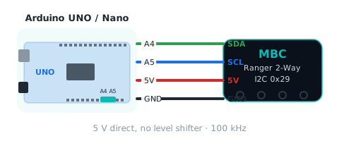
| Sensor | Arduino UNO / Nano | Arduino R4 | ESP32 |
|---|---|---|---|
| SDA | A4 | SDA | GPIO 21 |
| SCL | A5 | SCL | GPIO 22 |
| 5V | 5V | 5V | 5V |
| GND | GND | GND | GND |
Works directly with 5 V hosts, no level shifter; two products with the same address cannot share a bus (re-address one with F8 first).
Value table
Each id returns one int16; click an id for the six-host reading and figure.
| Id | Value | Range | Meaning |
|---|---|---|---|
01 |
left distance (cm) leftCm |
0~120 cm | distance from the left sensor, 0~120 cm (left = sensor 0 seen from behind the robot); 120 = nothing in range / sensor failed |
02 |
right distance (cm) rightCm |
0~120 cm | distance from the right sensor, 0~120 cm (right = sensor 1); 120 = nothing in range / sensor failed |
03 |
nearer distance (cm) nearCm |
0~120 cm | the smaller of left and right, 0~120 cm |
04 |
left distance (mm) leftMm |
0~1200 mm | left sensor distance 0~1200 mm; 1200 = nothing in range / sensor failed |
05 |
right distance (mm) rightMm |
0~1200 mm | right sensor distance 0~1200 mm; 1200 = nothing in range / sensor failed |
06 |
init bitmap initOk |
0~3 bit | bit0 = left, bit1 = right; 1 = that sensor initialised at power-on (no retry); 3 = both OK |
07 |
fault bitmap fault |
0~3 bit | bit0 = left, bit1 = right; 1 = that sensor is currently failing (I2C error or no update for 200 ms); its distance reads 120 / 1200 |
08 |
average distance (mm) avgMm |
0~1200 mm | (left mm + right mm) / 2, 0~1200; same number as EV3 mode 3 and the 3rd value of SPIKE mode 6 |
Status flags F3
| bit | Name | Meaning |
|---|---|---|
| b0 | ready (ready) |
1 once both sensors are initialised and snapshots are running |
| b1 | any sensor failed (fault) |
1 if any sensor failed to initialise, has an I2C error or no update for 200 ms (07 ≠ 0 or 06 ≠ 3) |
Shared registers
| Id | Name | Meaning |
|---|---|---|
F0 |
device ID | low byte = factory I2C address (unchanged after re-addressing), high byte = hw[0] (channels / sensors / variant) |
F1 |
protocol version | 2 for this release (same number reported in SPIKE mode 8 v[1]) |
F2 |
firmware version | major×100 + minor (e.g. 102 = 1.2) |
F3 |
status flags | b0 = ready; other bits per product (see flags) |
F4 |
update counter | +1 every 10 ms snapshot, wraps 0~255 (2.56 s per cycle, not usable for reboot detection; frozen = module busy) |
F5 |
uptime seconds | seconds since boot, saturates at 32767 (~9 h); a drop means the module rebooted |
F8 |
change I2C address | [F8][new 0x08 |
EF |
reboot | [EF][0xA5]; mBlock sends ACK first, then reboots |
Single-file helper functions
No library to install. Paste it in two parts: part ① (2 lines) at the top of the sketch, part ② at the bottom. #include <Wire.h> and MBC_NONE must appear before setup() uses them; pasting everything at the bottom will not compile.
① At the top of your sketch (before setup())
#include <Wire.h>

const int16_t MBC_NONE = -32768;   // no answer / undefined id
② At the bottom of your sketch (after loop())
// read k consecutive values (k ≤ 16) starting at id, int16 little-endian
bool mbcReadMany(uint8_t addr, uint8_t id, uint8_t k, int16_t *out) {
  Wire.beginTransmission(addr);
  Wire.write(id);
  if (Wire.endTransmission() != 0) return false;
  delay(2);                                        // always wait 2 ms (ESP32 products cannot clock-stretch)
  if (Wire.requestFrom(addr, (uint8_t)(k * 2)) != (uint8_t)(k * 2)) return false;
  for (uint8_t i = 0; i < k; i++) {
    uint8_t lo = Wire.read(), hi = Wire.read();
    out[i] = (int16_t)(lo | (hi << 8));
  }
  return true;
}

// read one value; MBC_NONE when nothing answers
int16_t mbcRead(uint8_t addr, uint8_t id) {
  int16_t v;
  return mbcReadMany(addr, id, 1, &v) ? v : MBC_NONE;
}

// write a command (0~3 parameters)
// with 2 parameters whose first is 0, write (uint8_t)0, e.g. mbcWrite(ADDR, 0xF8, (uint8_t)0x00, 0xFF); otherwise it clashes with the array form below and will not compile
void mbcWrite(uint8_t addr, uint8_t id, const uint8_t *args, uint8_t n) {
  Wire.beginTransmission(addr);
  Wire.write(id);
  for (uint8_t i = 0; i < n; i++) Wire.write(args[i]);
  Wire.endTransmission();
}
void mbcWrite(uint8_t addr, uint8_t id) { mbcWrite(addr, id, nullptr, 0); }
void mbcWrite(uint8_t addr, uint8_t id, uint8_t a) { mbcWrite(addr, id, &a, 1); }
void mbcWrite(uint8_t addr, uint8_t id, uint8_t a, uint8_t b) { uint8_t p[2] = {a, b}; mbcWrite(addr, id, p, 2); }
void mbcWrite(uint8_t addr, uint8_t id, uint8_t a, uint8_t b, uint8_t c) { uint8_t p[3] = {a, b, c}; mbcWrite(addr, id, p, 3); }

// wait until ready (F3 bit0 = 1), at most ms milliseconds
bool mbcWaitReady(uint8_t addr, unsigned long ms) {
  unsigned long t0 = millis();
  while (millis() - t0 < ms) {
    int16_t st = mbcRead(addr, 0xF3);
    if (st != MBC_NONE && (st & 1)) return true;
    delay(20);
  }
  return false;
}
Example: print the whole value table
// helper part ①
#include <Wire.h>

const int16_t MBC_NONE = -32768;   // no answer / undefined id

const uint8_t ADDR = 0x29;

void setup() {
  Serial.begin(115200);
  Wire.begin();
#if defined(WIRE_HAS_TIMEOUT)
  Wire.setWireTimeout(25000, true);   // AVR: never hang when the module is silent
#endif
  if (!mbcWaitReady(ADDR, 2000)) Serial.println("module not found: check wiring and address");
  Serial.print("ID 0x"); Serial.println(mbcRead(ADDR, 0xF0), HEX);   // low byte address, high byte hw[0]
  Serial.print("FW ");    Serial.println(mbcRead(ADDR, 0xF2));
}

void loop() {
  Serial.print("leftCm: "); Serial.println(mbcRead(ADDR, 0x01));   // left distance (cm)
  Serial.print("rightCm: "); Serial.println(mbcRead(ADDR, 0x02));   // right distance (cm)
  Serial.print("nearCm: "); Serial.println(mbcRead(ADDR, 0x03));   // nearer distance (cm)
  Serial.print("leftMm: "); Serial.println(mbcRead(ADDR, 0x04));   // left distance (mm)
  Serial.print("rightMm: "); Serial.println(mbcRead(ADDR, 0x05));   // right distance (mm)
  Serial.print("initOk: "); Serial.println(mbcRead(ADDR, 0x06));   // init bitmap
  Serial.print("fault: "); Serial.println(mbcRead(ADDR, 0x07));   // fault bitmap
  Serial.print("avgMm: "); Serial.println(mbcRead(ADDR, 0x08));   // average distance (mm)
  Serial.println();
  delay(200);
}

// paste part ② of the helper functions below
Sources and assumptions
Generated by _build/gen-reference.mjs from _build/protocol/tof2.json (single source of truth, transcribed from the 2026-10-21 protocol decisions).
- 共識 #8:08 左右平均 mm 補進 I2C/mBlock 值表(定案 §5 已列)。
- 0x22 命令 4
12 不動(4 左、5 右、6 最近、711 = 0、12 = 最近);schema 不收 11/12,所以 12 只寫在 03 的 note。 - EV3:模式 0、2、4 鎖住(照盤點);模式 1 改 [左,右]×4(index 0/1 各代表左右)、模式 3 改平均 mm、模式 5 改 [左 mm, 右 mm];模式 1 描述表宣告 int8 −100~100,cm×100/120 在範圍內。
- SPIKE:0/5/7/9 鎖住,另加模式 3 鎖住(網站 sensors/tof2/index.md read(3) = 左/右 cm,共識 #11);模式 6 改 [左 mm, 右 mm, 平均 mm];模式 1、2、4、8 維持不動;模式 8 v[0] 改 ID|hw[0]<<8(統一後共用函式)。
- 「左」= 站在車後往前看的左(第 0 顆,XSHUT PA6);韌體只有 L/R 巨集名,盤點檔標為推測。
- 沒有寫入命令;F8 換位址/EF 重開機用共用的。
- Pin table uses each board's common defaults (ESP32: change with
Wire.begin(sda, scl)).