
Gamepad Receiver PS4/PS5 × mBlock 5 (Makeblock edition)
Back to Gamepad Receiver PS4/PS5
The Makeblock edition of the Gamepad Receiver PS4/PS5 plugs into an RJ25 port on mBot, Ranger, Orion or MegaPi and is read with the MBC Pro Sensors extension v2 blocks. Installation and usable ports per board: Makeblock extension.
SPIKEEV3Arduino I2CmBlockMATRIXmicro:bit
Wiring
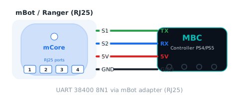
Sensor → mBot adapter → RJ25 port on the board (S1 = host TX, S2 = host RX). UART 38400 8N1.
Reporter blocks
| Block | Returns | Id | Meaning |
|---|---|---|---|
| Controller port [port] 16 buttons | 0~65535 bit | 01 |
all buttons in one 16-bit word (PSX layout): bit0 SELECT(SHARE), 1 L3, 2 R3, 3 START(OPTIONS), 4 up, 5 right, 6 down, 7 left, 8 L2, 9 R2, 10 L1, 11 R1, 12 triangle, 13 circle, 14 cross, 15 square; 1 = pressed; 0 when not connected |
| Controller port [port] D-pad | 0~15 bit | 02 |
up 1, right 2, down 4, left 8, added when pressed together (0~15) |
| Controller port [port] shape buttons | 0~15 bit | 03 |
triangle 1, circle 2, cross 4, square 8, added when pressed together (0~15) |
| Controller port [port] shoulder buttons | 0~15 bit | 04 |
L2 1, R2 2, L1 4, R1 8, added when pressed together (0~15) |
| Controller port [port] function buttons | 0~15 bit | 05 |
SELECT(SHARE) 1, L3 2, R3 4, START(OPTIONS) 8, added when pressed together (0~15) |
| Controller port [port] gamepad connected? | 0~1 | 06 |
1 = gamepad connected and data seen within 300 ms, 0 = not connected (buttons 0, sticks centred while disconnected) |
| Controller port [port] battery | 0~100 % | 07 |
gamepad battery 0~100 (always 0 on the PS2 receiver) |
| Controller port [port] L2 analog | 0~255 | 08 |
L2 trigger depth 0~255 (0 when not connected) |
| Controller port [port] R2 analog | 0~255 | 09 |
R2 trigger depth 0~255 (0 when not connected) |
| Controller port [port] system buttons | 0~3 bit | 0A |
b0 PS button, b1 capture (PS5 mute) button; 0 when not connected (always 0 on PS2) |
| Controller port [port] gamepad type | 0~4 | 0B |
0 none, 1 PS2 digital, 2 PS2 analog, 3 PS4, 4 PS5 (or other) |
| Controller port [port] stick [axis] | -100~+100 | 10~13 |
10 LX, 11 LY, 12 RX, 13 RY: −100 to +100, 0 = centre, right/up positive; 0 when not connected |
| Controller port [port] [button] pressed? | true/false | 01 |
one button split out of 16 buttons 01 (PSX order); menu: ✕ ● ▲ ■ up down left right L1 R1 L2 R2 L3 R3 SELECT START |
Command blocks
| Block | Id | Meaning |
|---|---|---|
| Controller port [port] rumble [strength] | E5 |
[strength 0~255], 0 = stop; 200 ms per call (ignored by PS2) |
| Controller port [port] light bar colour [R] [G] [B] | E6 |
[R][G][B] each 0~255, exactly 3 bytes; remembered until connected; default blue (0,0,255) (ignored by PS2) |
| Controller port [port] update all values | FD |
reads the whole value table into a cache (FD pack-all); reporter blocks within the next 10 ms use the cache instead of asking one by one |
Status blocks
The extension exposes each F3 bit as a boolean block:
| bit | Name | Meaning |
|---|---|---|
| b0 | ready (ready) |
always 1 |
| b1 | gamepad connected (connected) |
same as value 06 (linkActive) |
Packet format (for your own decoder)
| Action | Format |
|---|---|
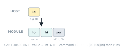
| Read one value | 主機送 [編號] → 回 [值低][值高][編號^值低^值高] |
| Write command | 寫入命令 E0~EE:收齊參數後回 [00][00][編號] 再執行;20 ms 內沒收齊就丟棄 |
| Unknown id | [00][80][編號^0x80](= -32768) |
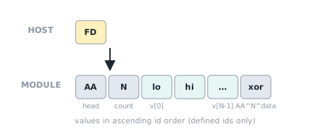
| Pack all (FD) | Send [FD] → reply [AA][0F][15 × int16 LE][xor], xor = AA ^ N ^ all data bytes; content = this value table in ascending id order (shared ids and commands excluded). The extension fetches it once and serves blocks from a 10 ms cache. |
| Shared ids | F0 device ID, F1 protocol version, F2 firmware version, F3 status flags |
Sources and assumptions
Generated by _build/gen-reference.mjs from _build/protocol/ps4.json (single source of truth, transcribed from the 2026-10-21 protocol decisions).
- 值表、命令、旗標與 PS2 完全相同(mBlock 定案「兩款相同」+I2C 定案 §3/§4);只有 hw0 = 2、model = PS4、E5/E6 有作用。
- D3:SPIKE 模式 0 教育版 byte 6~7、模式 6 v[2]、模式 9 v[6] 的 button16 都是 PSX 排列(#65 已把 PS4 改成 PSX,盤點檔寫的 Bluepad32 排列已過時)。
- 0x22 命令 4 同時裝方向鍵(低 nibble)與形狀鍵(高 nibble)、命令 5 裝肩鍵(低)與功能鍵(高);JSON 只能把一個命令掛在一個值上,所以掛在 02/04,03/05 的 ch22 = null(內容寫在 02/04 的 note)。SPIKE 模式 0/1/2/9 的 nibble 也用同樣方式在 note 說明。
- 搖桿:I2C/mBlock 送 ±100;EV3/0x22送 0
99(50 = 中間)、SPIKE 送 19(5 = 中間),不是線性 offset,主機端各自換算(網站範例已是這樣)。 - EV3 模式 3 = 方向鍵 | 形狀鍵<<4 | 已連線<<8(#67 新增 bit8);模式 4 內容不變([方向鍵, LX, 形狀鍵, LY]);模式 5 改送裝置 ID 格式 B [0x42 | 2<<8, 韌體版]。
- SPIKE 模式 3 改 [已連線, 電量, 0](3×int8)、模式 8 改 [0x42 | 2<<8, 協議版 2, 韌體版, 更新序號];其餘空模式 1、2、4、6 維持現狀。
- ESP32 從機不能時脈延展:I2C v2 在 onReceive 就預載從該編號起 32 B;0x22照 MATRIX 定案 §5 #2 預載最新一包,待上機。
- I2C 0A 系統鍵 b1 = 擷取鍵(v1 0x15 放在 b3,v2 改 b1,照 I2C 定案 §4)。
- Block wording follows the v2.0.0 extension generator
build_mext.js; this page is generated from the same JSON.